ENKOFORM VMK
Construcción
23
ENKOFORM VMK
3.2.1 Assembly of LIFTING BRACKET E V-100:
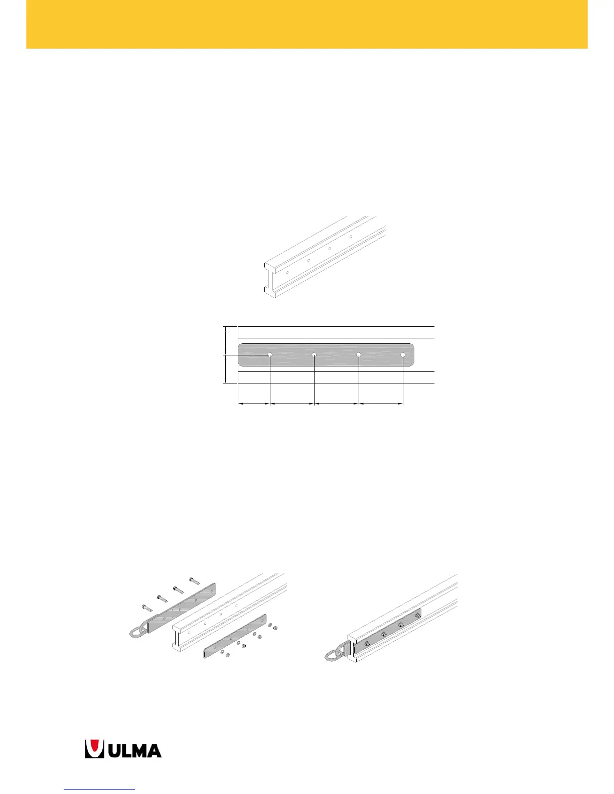
1. Make 4 holes of 17 mm diameter in the centre to the BEAM VM20 (in case the BEAM VM20 has no holes).
The gap between the holes is 160 mm, and the gap from the 1st hole to the corner of the BEAM VM 20
will be 115 mm.
(The inner plate (the one of the lifting bracket with no ring) will be used as pattern. This plate will be
placed levelled with the corner of the BEAM VM 20). (Repeat this operation with 2 VM 20 BEAMS per
PANEL).
BEAM VM 20 with 4 holes of 17 mm.
115 160 160 160
==
BEAM VM 20 with the plate of the LIFTING BRACKET E V-100 that will be used as pattern to make the holes.
2. E V-100 LIFTING BRACKETS will be assembled on the BEAM VM 20 where previously 4 holes have been
done. To do so, the nuts of the E V-100 LIFTING BRACKETS will be previously released and the plate
removed. The stem of the BEAM VM 20 will be between the two plates of the E V-100 LIFTING BRACKETS.
Finally, the nuts are tied up. The bracket will be assembled in such a way that the ring will be 5 cm out of
the BEAM VM 20, and the other plate levelled. (Repeat this operation in 2 BEAMS VM20 per PANEL).
Placement of the E V-100 LIFTING BRACKETS in a BEAM VM 20 where holes have been previously made.