ENKOFORM VMK
Construcción
24
ENKOFORM VMK
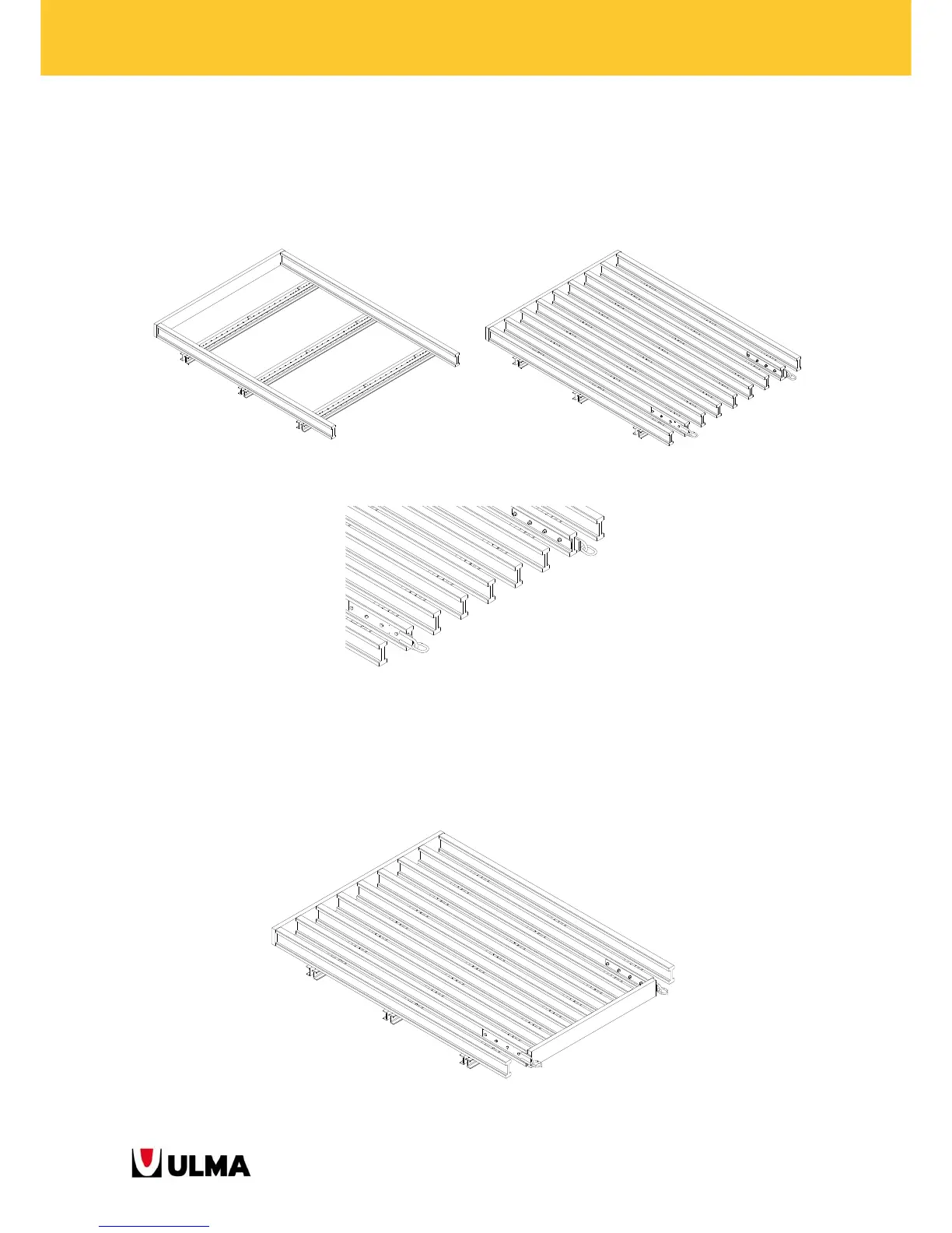
3. Continue assembling the PANEL according to what it is indicated in the assembly draft. Place the VM20
BEAMS that have the E V-100 LIFTING BRACKETS included in the indicated position. Take into account that
the VM20 BEAMS that have the E V-100 LIFTING BRACKETS will have to be placed in such a way that the
plates with rings will be in the outwards on both sides.
Assembly of PANEL, first with just 2 VM 20 BEAMS joined to MK-120 WALER and then will all the BEAMS.
The E V-100 LIFTING BRACKETS are placed in such a way that the plates remain faced outwards.
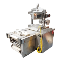
4. Place a 200x50 mm section wood plank between the E V-100 LIFTING BRACKETS. This plank will be
screwed to all the VM 20 BEAMS.
Screw type: D6x80 mm with countersinking head.
PANEL with a PLANK placed between the E V-100 LIFTING BRACKETS.