Step 3: clamp assembly Assembling the material feeder78
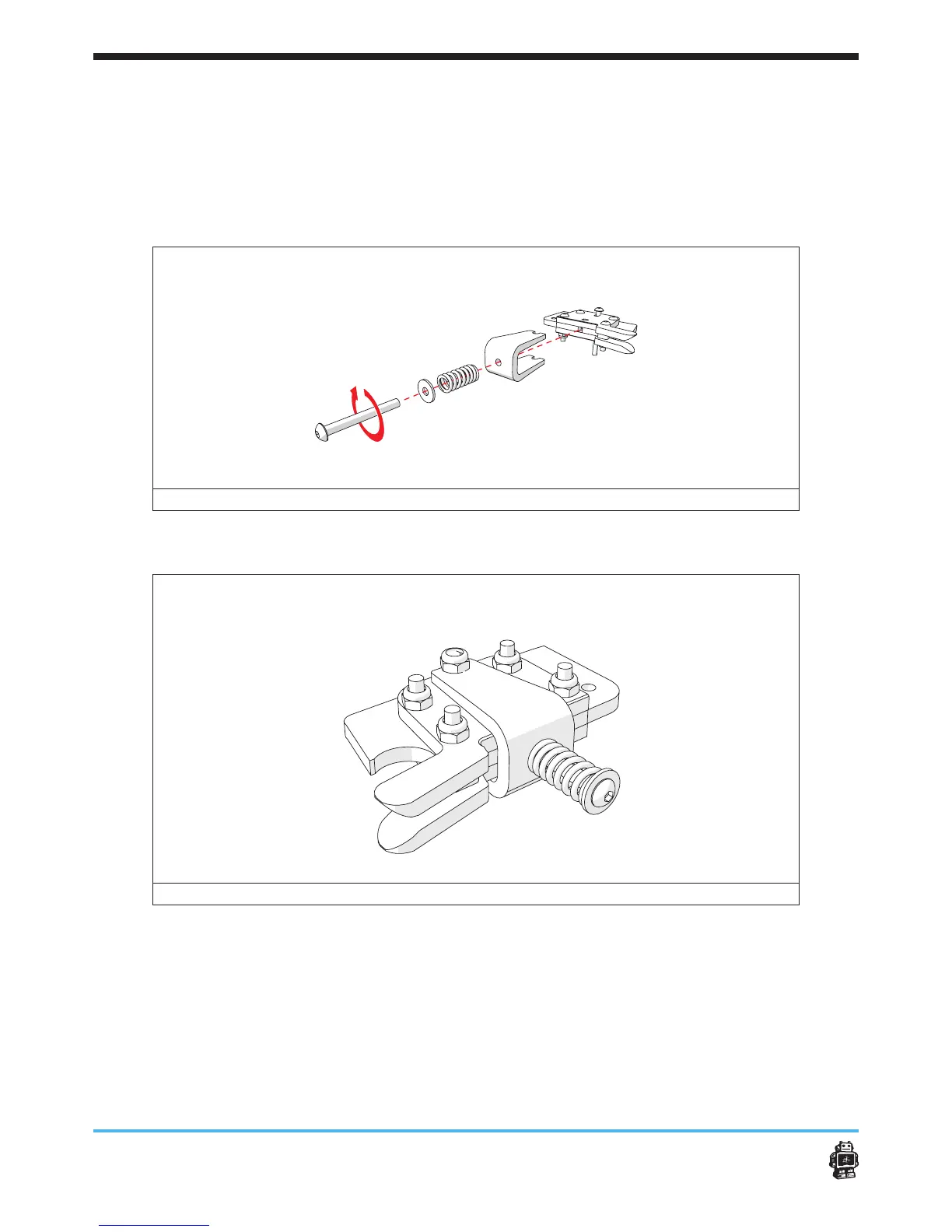
6. Place the U-Bracket on side of the clamp assembly, see image 97.
7. Attach a spring and a washer on the hole of the U-Bracket.
Use a bolt M3 x 20mm.
5 Notice: because you have to push the spring, it can take some force.
5 Notice: the spring should stick out about 11mm.
image 97: placing the U-Bracket on the clamp assembly
The result must look like this, see image 108.
image 98: result after attaching the U-Bracket on the clamp assembly
(for action 9-10 see image 99)
8. Attach the clamp assembly with U-Bracket on the main body of the
drive mechanism.
Use ONE bolt M3 x 20mm and ONE lock nut.
5 Notice: do not screw too tight, the clamp assembly with U-Bracket
must be able to move.
5 Notice: make sure the lock nut is NOT placed on the side of the gear.
9. Connect the lever to the main body of the drive mechanism.
 Loading...