Page 3-6
Maintenance -3.7-SwitchAdjustments
SL20
3.7 S
WITCH
A
DJUSTMENTS
P
ROXIMITY
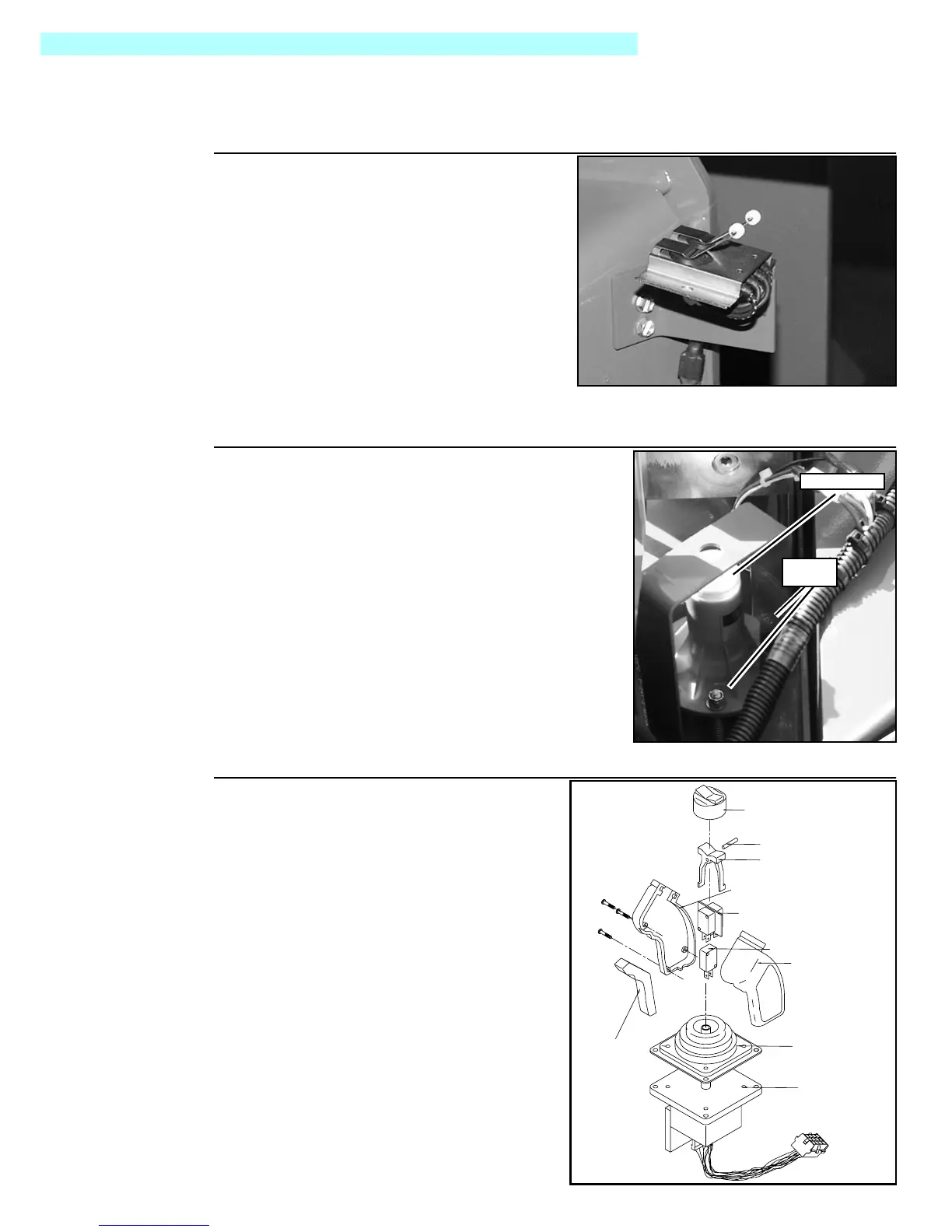
Figure 3-7:
Proximity Switch
The proximity switch is located on the left side of
the chassis above the drive wheel. When the
machine is lowered and the tabs are depressed,
high speed drive is available. When the machine
is raised, the tabs deactivate, and the machine
will drive in creep speed.
ADJUSTMENT
1. Adjust proximity switch so machine oper-
ates at creep speed when platform is
raised above 1.6 m [6ft.]).]
T
ILT
S
ENSOR
Figure 3-8:
Tilt Sensor
INTRODUCTION
The tilt sensor has three wires; red-power (24 v in),
black-ground, white-output (24 v out). To verify the sen-
sor is working properly there is a red LED under the sen-
sor that lights up when the sensor is not level.
ADJUSTMENT
1. Place machine on firm level surface ± ¼°.
2. Use the Inclinometer (P/N: 10119-000-00) to
ensure front and rear of chassis is level ± ¼°.
3. Adjust the three leveling screws until the bubble is
centered in the inner circle.
PQ C
ONTROL
H
ANDLE
Figure 3-9:
PQ Control Handle
1. Remove Handle if necessary from Plat-
form Control box.
2. Remove and replace defective parts.
Refer to Section 6 for repair parts num-
bers.
Bubble Level
Leveling
Screws
Boot, Steering Rocker
Rocker Pin
Rocker, Steering
Right Handle Half
Steering Switch (2)
Switch, Interlock
Left Handle Half
Boot, Handle
Lever, Interlock
Hall Effect Device

 Loading...


