Page 3-17
Maintenance -3.16-BrakeCylinder
SL20
3.16 B
RAKE
C
YLINDER
R
EMOVAL
1. Block the wheels to prevent the work platform from rolling.
2. Loosen the wheel lug nuts. Use a 1.3 metric ton (1.5 imperial ton) capacity jack to raise the
work platform until the wheel being repaired is off the ground.
3. Install support blocks to prevent the work platform from falling if the jack fails.
4. Remove the wheel lug nuts and the wheel.
5. Disconnect the hose assemblies from the drive motor and brake cylinder. Cap the openings
to prevent foreign material from entering.
NOTE: The motor mount
assembly is heavy. The use of a
support device is recommended.
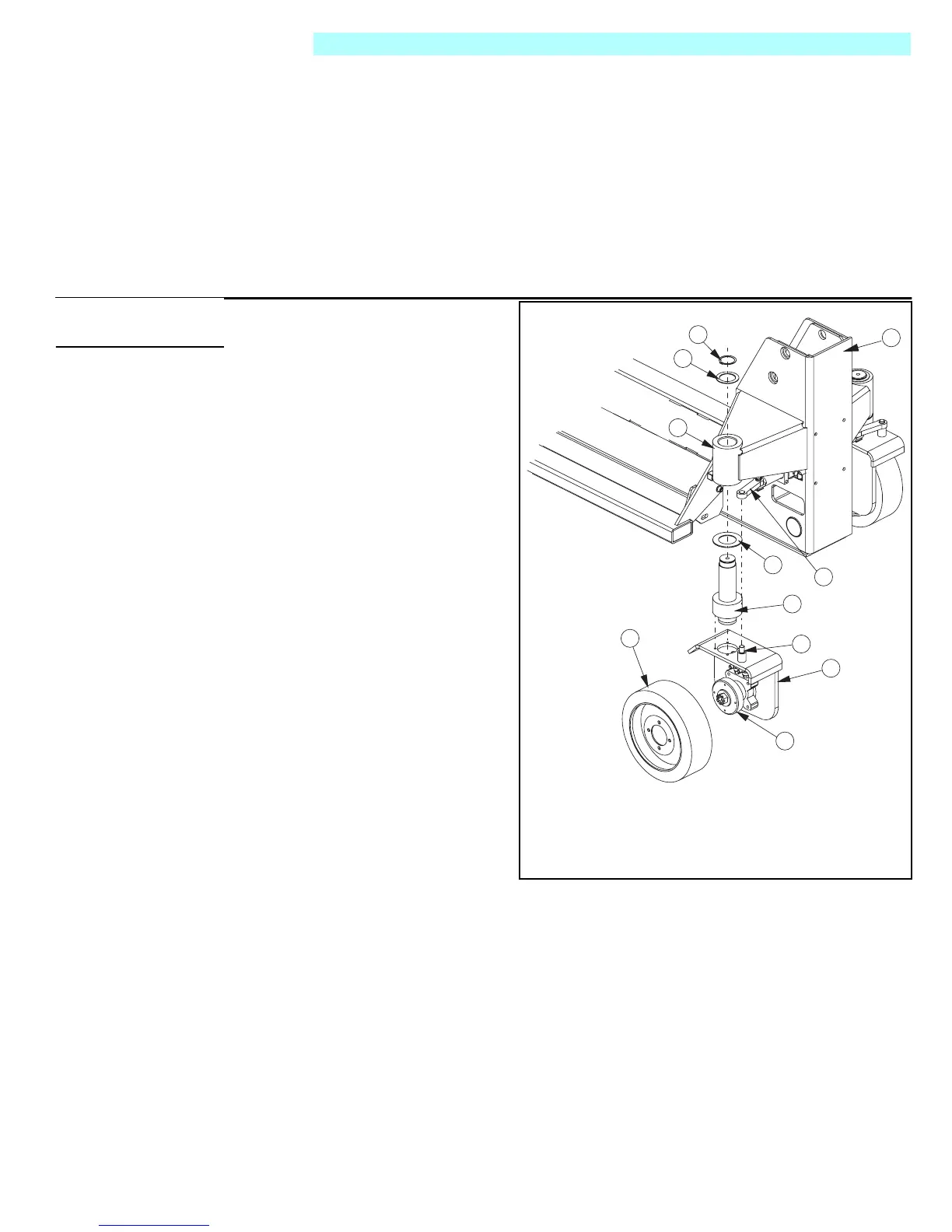
Figure 3-18:
Brake Cylinder
6. Remove the retaining ring and
brake retaining washer from the
top of the brake cylinder.
7. Slowly lower the motor mount
assembly and guide the brake
cylinder out of the brake cylinder
mount. The spindle thrust washer
will come off with the brake cylin-
der.
8. Lay the motor mount assembly
on its side to access the brake
cylinder mounting screws.
9. Remove the mounting screws
and remove the cylinder from the
motor mount.
I
NSTALLATION
1. Install the brake cylinder assem-
bly onto the motor mount assem-
bly. Apply Loctite 242 and torque
thecapscrewsto41N-m(30
ft.lbs.).
2. Place the spindle thrust washer
onto the spindle of the brake cyl-
inder assembly.
3. Raise the motor mount and brake
cylinder assembly into the brake
cylinder mount.
4. When the brake cylinder is
almost fully inserted into the brake cylinder mount, align the steering arm with the steering
arm spindle.
5. Raise the unit until it is fully inserted into the brake cylinder mount.
6. Install the brake cylinder retaining washer and secure with snap ring.
7. Connect the hose assemblies.
8. Install the wheel with lug bolts onto the hub. Torque to 108 N-m (80 ft. lbs.).
9. Remove blocks, lower the jack, and remove. Operate the brakes and drive system check for
leaks.
10. Drive machine for 20 minutes and retorque wheel lug bolts. Check for leaks.
11. Operate the drive circuit and check that the shaft retracts and clears the wheel. Check for
leaks.
10
11
9
8
6
5
4
7
3
2
1
1. Wheel
2. Hub and
Drive Motor
3. Motor Mount
4. Steering Arm Mount
5. Brake Cylinder
6. Spindle Thrust Washer
7. Steering Linkage
8. Brake Cylinder Mount
9. Brake Retaining Washer
10. Retaining Ring
11. Chassis
Seal Kit 101015-010

 Loading...


