Page 3-14
Maintenance - 3.13 - Hydraulic Power Unit
SL20
3.13 H
YDRAULIC
P
OWER
U
NIT
R
EMOVAL
NOTE: If the hydraulic tank has
not been drained, suitable
means for plugging the hoses
should be provided to prevent
excessive fluid loss.
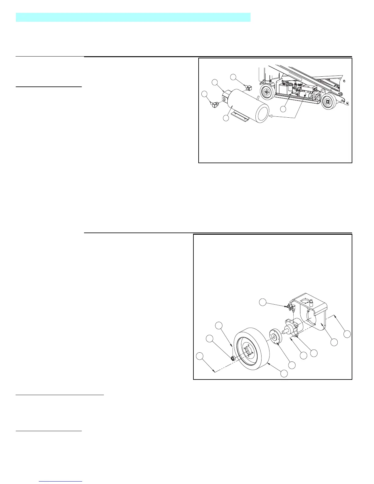
Figure 3-15:
Hydraulic Power Unit
1. Disconnect the negative battery
cable.
2. Mark, disconnect, and plug the
hose assemblies.
3. Mark and disconnect the motor
cables.
4. Loosen the capscrews and
remove the power unit from the
control module.
I
NSTALLATION
1. Place the power unit into the
control module. Torque the
mounting screws to 41 N-m (30 ft.lbs.).
2. Unplug and reconnect the hydraulic hoses. Reconnect the motor cables and negative bat-
tery cables.
3. Check the oil level in the hydraulic tank before operating the work platform.
3.14 H
YDRAULIC
D
RIVE
M
OTORS AND
H
UBS
Figure 3-16:
Hydraulic Drive Motor
R
EMOVAL
1. Park the work platform on firm
level ground then block the
wheels to prevent the work
platform from rolling.
2. Loosen the wheel lug bolts on
the front corner to be raised.
3. Use a 1.3 metric ton (1.5 impe-
rial ton) capacity jack to raise
the desired corner. Position
blocks under the raised corner
to prevent the work platform
from falling if the jack fails.
4. Remove the wheel lug bolts
and wheel.
5. Remove the cotter pin, slotted
nut, and hub. If necessary use
a wheel puller to remove the hub.
NOTE: Before disconnecting
hoses, thoroughly clean off all
outside dirt around fittings.
(After disconnecting hoses and
before removing from vehicle,
IMMEDIATELY plug port holes.)
6. Tag, disconnect, and plug the hose assemblies to prevent foreign material from entering.
7. Remove the locknuts, capscrews, and drive motor from the motor mount.
2
1
3
4
5
1. Pump
2. Outlet Hose Fitting
3. Inlet Hose Fitting
4. Electric Motor
5. Control Module
1
2
3
4
5
6
7
8
9
10
1. Motor Mount
2. Drive Motor
3. Capscrew
4. Hub
5. Wheel
6. Wheel Lug Bolt
7. Slotted Nut
8. Cotter Pin
9. Hose Fitting
10. Lock Nut

 Loading...


