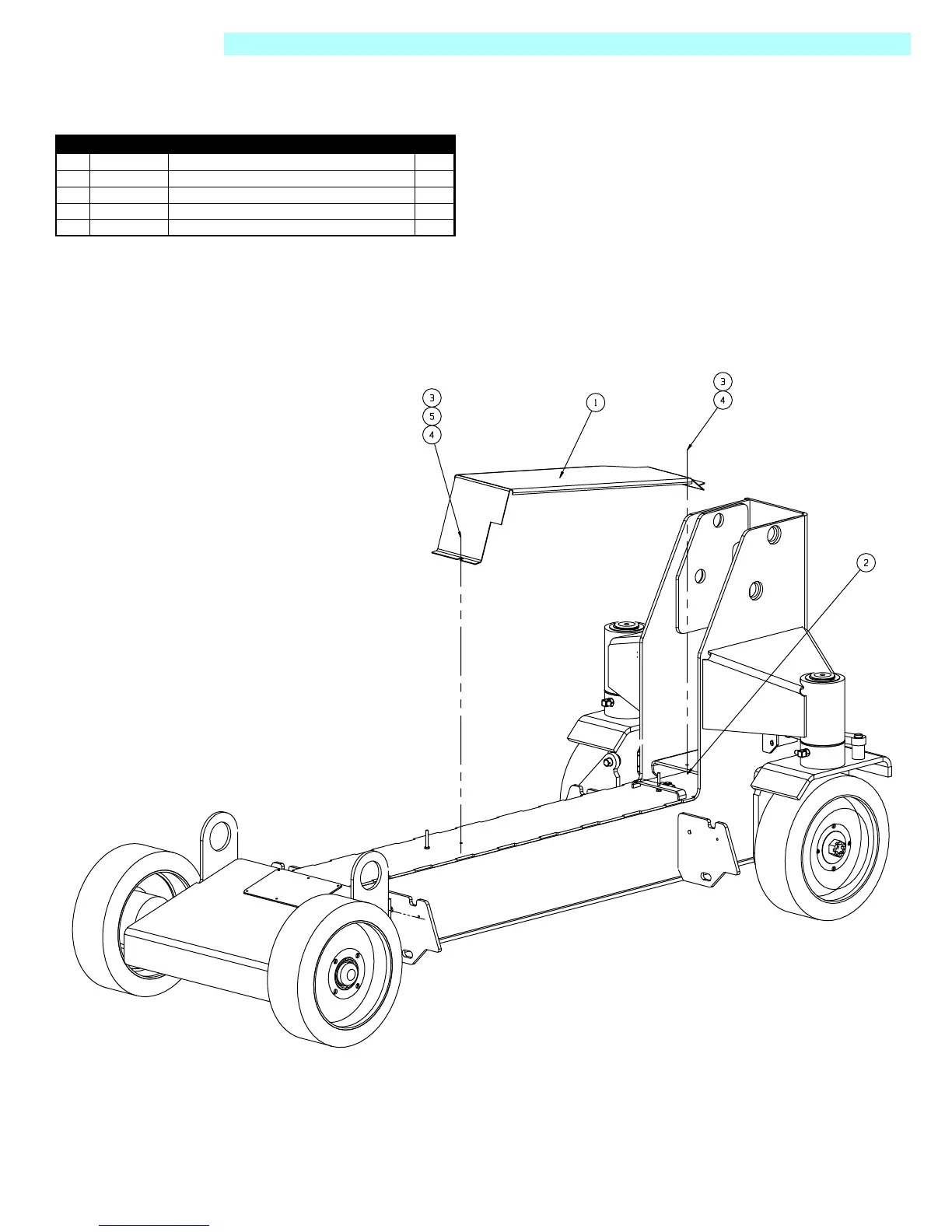
Home
Upright
Lifting Systems
SL20 Series
Upright SL20 Series User Manual
5
of 1
of 1 rating
104 pages
Give review
Manual
Specs
To Next Page
To Next Page
To Previous Page
To Previous Page
Loading...
Page
6-
9
Illu
stra
ted
Par
ts
B
reak
dow
n
-
Cover
Plate
Assembly
SL20
Cover
P
lat
e
A
ss
em
bly
030957
-000
Item
Pa
rt
Descr
iption
QTY
.
1
030957-0
01
CO
VER
PLA
TE
1
2
011248-0
04
NUT
HEX
ES
NA
1/4-20
UNC
1
3
011252-0
08
SCRE
W
HHC
1/4-20
U
NC
X
1
2
4
011240-0
04
WA
SHER
1/
4
STD
FLA
T
2
5
011238-0
04
WA
SHER
1/
4
SPLIT
LOCK
1
70
72
Table of Contents
T Cable of
5
Default Chapter
5
Table of Contents
5
Introduction
11
Purpose
11
Scope
11
General Description
11
Figure 1-1: SL 20 Work Platform
11
Purpose and Limitations
11
Safety Rules
13
Introduction
14
Pre-Operation & Safety Inspection
14
Figure 2-2: Emergency Lowering Knob
14
Operation
15
Figure 2-4: Platform Extension
15
Platform Extension
15
Steering
15
Travel with Platform Lowered
15
Elevating Platform
16
Emergency Lowering
16
Lowering Platform
16
After Use each Day
17
Transporting Work Platform
17
Figure 2-5: Transporting the Work Platform
17
By Truck
18
Maintenance
18
Figure 2-6: Blocking the Elevating Assembly
18
Battery Maintenance
19
Figure 2-7: Power Module
19
Preventative Maintenance
20
Preventative Maintenance Checklist
21
Preventative Maintenance Key
21
Preventative Maintenance Report
21
Specifications
22
Maintenance
23
Introduction
23
General Procedures
23
Terminology
23
Date Code Identification on Hoses
23
Special Tools
24
Deutsch Connectors
24
Figure 3-1: Deutsch Connector Kit
24
Figure 3-2: Plugs and Receptacles, Deutsch Connectors
24
Crimping
25
Female Connector (Receptacle)
25
Figure 3-3: Locking Finger, Deutsch Connector
25
Figure 3-4: Heavy Duty Deutsch Connector
25
Male Connector (Plug)
25
Releasing Locking Fingers
25
Removing Contact from Heavy Duty Plug
25
Blocking Elevating Assembly
26
Brace Installation
26
Brace Removal
26
Battery Maintenance
26
Battery Inspection and Cleaning
26
Figure 3-5: Blocking the Elevating Assembly
26
Battery Charging
27
Figure 3-6: Batteries and Charger
27
Switch Adjustments
28
Figure 3-7: Proximity Switch
28
Figure 3-9: PQ Control Handle
28
PQ Control Handle
28
Proximity
28
Tilt Sensor
28
Motor Controller and I/O Board Dip Switch Settings
29
Controller
29
Figure 3-10: Controller
29
Figure 3-11: I/O Board
29
I/O Board
29
Lubrication
30
Hydraulic Oil Tank and Filter
30
Figure 3-12: Hydraulic Oil Tank and Filter
30
Oil and Filter Replacement
30
Setting Hydraulic Pressures
31
Main Relief Valve
31
Lift Relief Valve
32
Overcenter Valve
32
Steering Relief Valve
32
Hydraulic Manifold
34
Assembly
34
Cleaning and Inspection
34
Disassembly
34
Installation
34
Removal
34
Figure 3-14: Hydraulic Manifold, Exploded View
35
Hydraulic Power Unit
36
Figure 3-15: Hydraulic Power Unit
36
Figure 3-16: Hydraulic Drive Motor
36
Installation
37
Removal
37
Wheel Bearings
37
Figure 3-17: Wheel Bearings
37
Installation
39
Removal
39
Brake Cylinder
39
Removal
40
Steering Cylinder
40
Cleaning and Inspection
40
Disassembly
40
Assembly and Installation
41
Figure 3-20: Steering Cylinder Assembly
41
Installation
41
Figure 3-21: Lift Cylinder Installation and Assembly
43
Assembly
44
Cleaning and Inspection
44
Depression Mechanism Cylinder
44
Disassembly
44
Figure 3-22: Depression Mechanism Cylinder Installation
44
Figure 3-23: Depression Mechanism Assembly
44
Removal
44
Adjustable Compression Tube
45
Depression Mechanism System Adjustment
45
Figure 3-24: Compression Tube Assembly
45
Installation
45
Disassembly
46
Electric Motor
46
Figure 3-25: Electric Motor Service
46
Inspection
47
Table 3-1: Fasteners
48
Table 3-2: Hydraulic Components
48
Torque Specifications
48
General Procedure
49
Introduction
49
Adjustment Procedures
50
Special Tools
50
Troubleshooting
50
Figure 4-1: Motor Controller
51
Table 4-1: LED Fault Codes
51
Upright Motor Controller Diagnostics
51
Measured Voltage at I/O Board
52
Table 4-2: Circuit Board Connectors
52
Troubleshooting
53
Electrical Troubleshooting
53
Table 4-3: Troubleshooting Guide: Electrical Schematics
53
Troubleshooting
54
Hydraulic Troubleshooting
54
Table 4-4: Troubleshooting Guide: Hydraulic Schematic
54
Schematics
55
Default Chapter
55
Introduction
55
Electric - Model
56
Figure 2-1: Chassis Controls
56
Figure 2-3: Platform Controls
56
Figure 3-13: Hydraulic Manifold
56
Legend: Electrical Schematic, 065616-023
56
Hydraulic Schematic
58
Legend: Hydraulic Schematic, 101180-020
58
Figure 5-1: Hydraulic Block
60
Figure 5-2: Plugs
61
I P Bllustratedartsreakdown
63
Final Assembly
64
Hydraulic Schematic
64
Basic Assembly
67
Figure 3-18: Brake Cylinder
68
Figure 3-19: Steering Cylinder
68
Chassis Assembly 101002-020
68
Cover Plate Assembly 030957-000
71
Linkage Assembly
72
Figure 3-8: Tilt Sensor
74
Control Module Assembly
74
Power Module Assembly
76
Control Valve Assembly
78
Platform Assembly
80
Roll out Deck Extension 10108-020
81
Hose Kit Installation
82
Lower Controls Assembly
83
Platform Control Assembly
84
Chassis Control Cable Assembly (J3) 101239-000
86
Control Cable Assembly (J1)
87
Valve Block Cable Assembly (J2) 101236-000
88
Hydraulic Tank Assembly
89
Label Kit Installation
90
Label Kit, German
92
Label Kit, French
94
Label Kit, Spanish
96
Power to Platform Option
98
Air to Platform Option
99
Horn Option
100
Beacon Assembly
101
5
Based on 1 rating
Ask a question
Give review
Questions and Answers:
Need help?
Do you have a question about the Upright SL20 Series and is the answer not in the manual?
Ask a question
Upright SL20 Series Specifications
General
Brand
Upright
Model
SL20 Series
Category
Lifting Systems
Language
English
Related product manuals
Upright SL26 Series
86 pages
Upright SL-26
12 pages
Upright SL-26N
12 pages
Upright SB60
179 pages
Upright X26N
24 pages
Upright X20N
102 pages
Upright MX19
90 pages
Upright TM12
84 pages
Upright ab62
24 pages
Upright X20W
24 pages
Upright AB38
24 pages
Upright X Series
16 pages