Page 4-4
Troubleshooting - 4.4 - Measured Voltage at I/O Board / Adjustment Procedures
SL20
4.4 M
EASURED
V
OLTAGE AT
I/O B
OARD
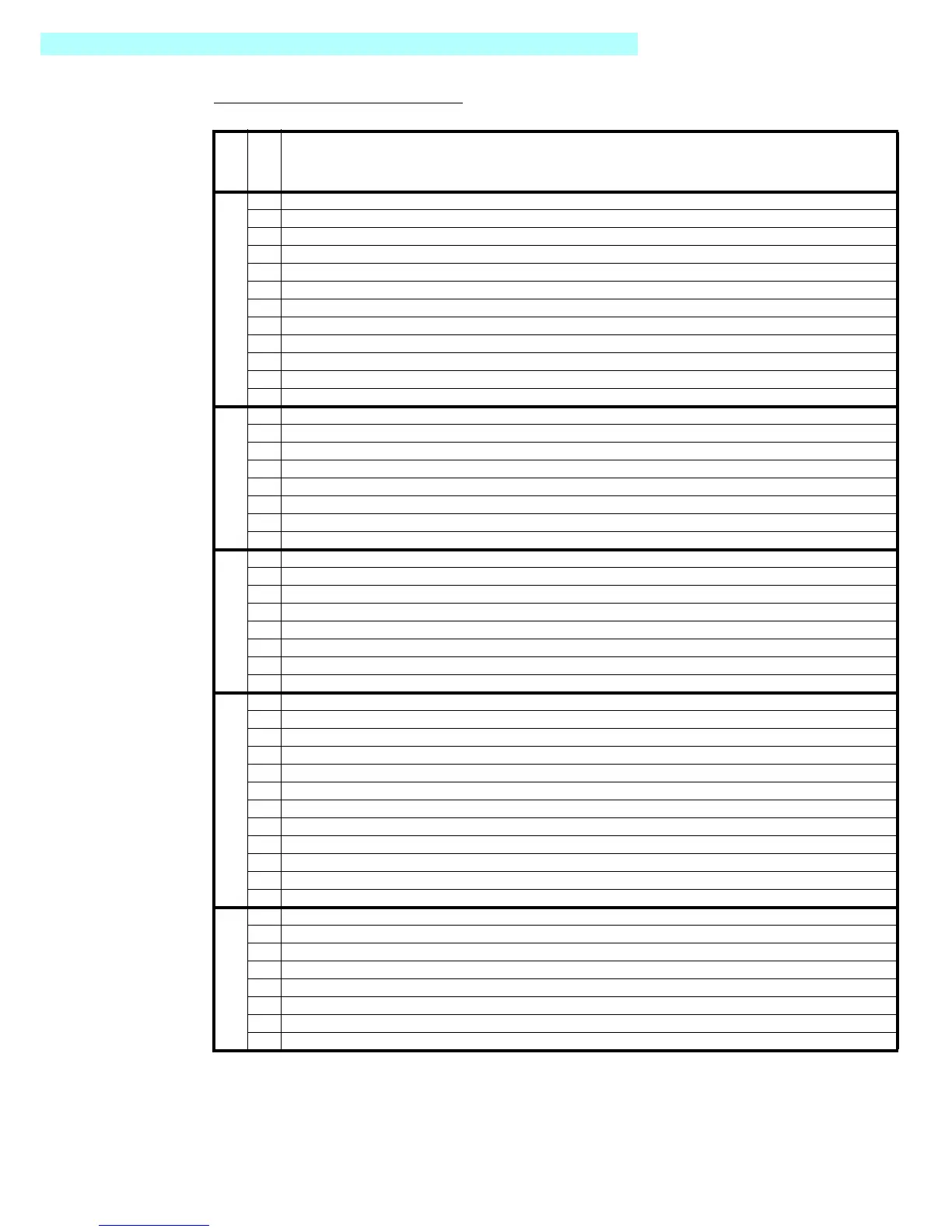
Table 4-2:
Circuit Board Connectors
CONNECTOR
PIN NUMBER
DESCRIPTION
J1
1 24 Volts = Lift Mode Active / 0 Volts = Lift Mode inactive
2 No Connection
3 24Volts=DriveAllowed/0Volts=DriveNotAllowed
4 24 Volts from Lower E-Stop / Lower E-Stop Not Depressed
5 24 Volts from Upper E-Stop / Lower and Upper E-Stops Not Depressed
6 24 Volts Out to Interlock Lever when Upper Controls Selected & Upper/Lower E-Stops Not Depressed
7 No Connection
8 24Volts=DriveForwardorLiftUp/0Volts=StopDriveForwardorLiftUp
9 24Volts=DriveReverseorLiftDown/0Volts=StopReverseDriveorLiftDown
10 Accelerator Input / 20K Pot / 3.5 Volts to 0 Volts, Minimum to Maximum Speed
11 24 Volts = Steer Left / 0 Volts = Stop Steer Left
12 24 Volts = Steer Right / 0 Volts = Stop Steer Right.
J2
1 Goes to 0 Volts to Activate Depression Mechanism Extend Solenoid / 24 Volts = Solenoid OFF
2 No Connection
3 24 Volt Supply for Solenoids
4 Goes to 0 Volts to Activate Forward Solenoid / 24 Volts = Solenoid OFF
5 Goes to 0 Volts to Activate Reverse Solenoid / 24 Volts = Solenoid OFF
6 Goes to 0 Volts to Activate Lift Up Solenoid / 24 Volts = Solenoid OFF
7 Goes to 0 Volts to Activate Steer Left Solenoid / 24 Volts = Solenoid OFF
8 Goes to 0 Volts to Activate Steer Right Solenoid / 24 Volts = Solenoid OFF
J3
1 Goes to 0 Volts to Activate Alarm / 24 Volts = Alarm OFF
2 24 Volts = Tilt Inactive / 0 Volts = Tilt Active
3 24 Volt Supply for Alarm, Tilt Sensor, Lift Down and Depression Mechanism Retract Solenoids
4 24 Volts = Below Height Limit / 0 Volts = Above Height Limit
5 Goes to 0 Volts to Activate Lift Down Solenoid / 24 Volts = Solenoid OFF
6 Goes to 0 Volts to Activate Depression Mechanism Solenoid / 24 Volts = Solenoid OFF
7 24Volts=HighSpeedActive/0Volts=LowSpeedActive
8 Battery Negative Supply for Tilt Sensor
J4
1 Goes to 0 Volts to Activate Line Contactor / 24 Volts = Line Contactor OFF
2 Supplies 24 Volts to Upper Control / Lower Control Switch
3 24 Volts = Lower Control Mode
4 Supplies 24 Volts to Ground Lift Switch when in Lower Control Mode
5 24 Volt Supply Output
6 Goes to 0 Volts to Activate Hour Meter / 24 Volts = Hour Meter Not Activated
7 24 Volts = Lift Up from Ground Control / 0 Volts = Lift Up OFF
8 24 Volts = Lift Down from Ground Control / 0 Volts = Lift Down OFF
9 24 Volt Supply Input from Battery via Lower E-Stop / Lower E-Stop Not Depressed
10 24 Volts from Upper Control Switch / 24 Volts = Upper Control Mode
11 Battery Negative Input to I/O Board
12 24 Volt Supply for Hour Meter and Line Contactor
J5
1 24 Volts power to Pin 1 of SC1000 (Key ON Power)
2 24 Volts = Command Controller to Drive / 0 Volts = Stop Controller Drive
3 24 Volts = Command Controller to Steer / 0 Volts = Steer OFF
4 24 Volts = Command Controller to Lift / 0 Volts = Stop Lift
5 24 Volts = Command Normal Speed / 0 Volts = Command Speed Cutback
6 24 Volts = Line Contactor OFF / 0 Volts = Line Contactor ON
7 24 Volts = No Direction Solenoid Allowed / 0 Volts = Direction Solenoid Allowed to Activate
8 Accelerator 3.5 Volts to 0 Volts / Minimum to Maximum Speed

 Loading...


