6-4a TL33 Work Platform
Schematics
Section
6.1 Electrical Schematic SERIAL NUMBERS: 1001 TO 1132
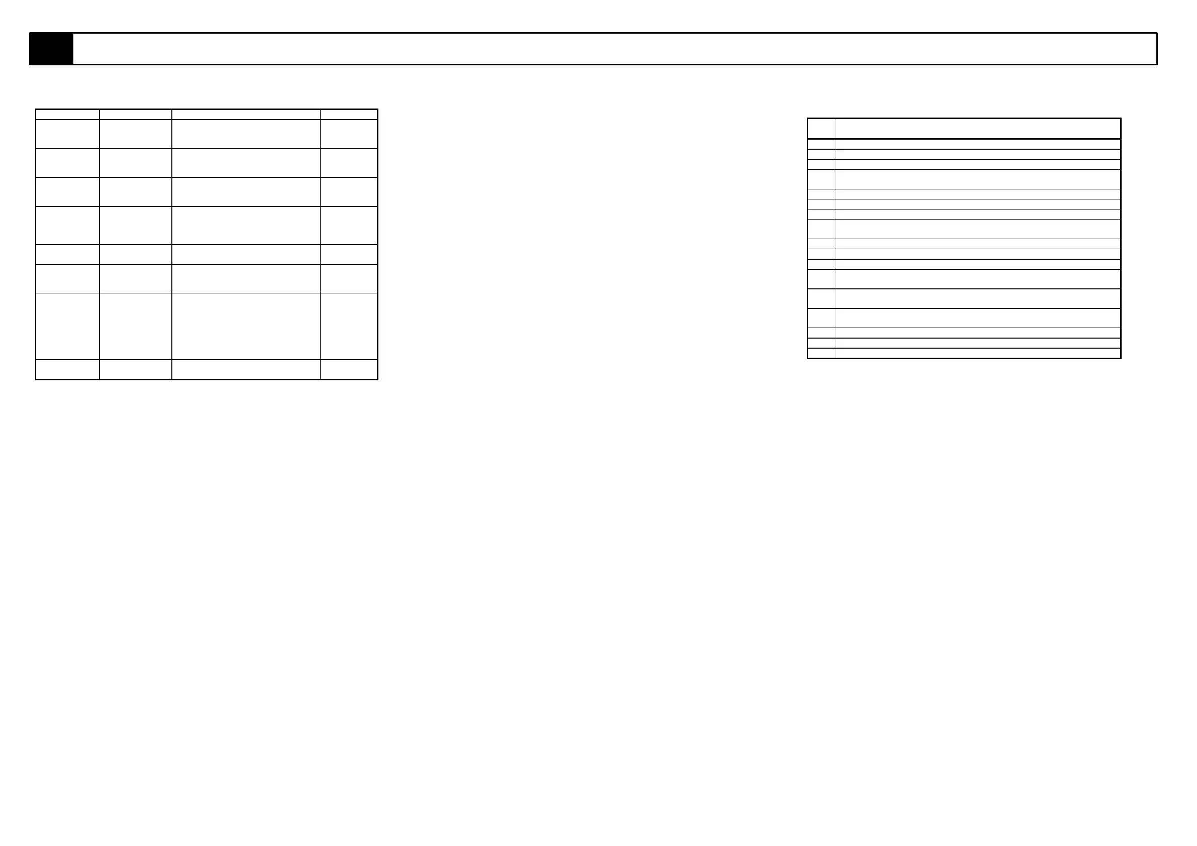
Table 6-1: Electrical Schematic Legend (Contd...)
REFERENCE NAME FUNCTION LOCATION
SW 1 Function switch
Lower Boom.
Sends power to the lower lift cylinder
solenoid which diverts oil to full bore or
annular side of lower lift cylinder.
Lower control
box.
SW 2 Function switch
Upper Boom.
Sends power to the upper lift cylinder
solenoid which diverts oil to full bore or
annular side of upper lift cylinder.
Lower control
box.
SW 3 Function switch
slew.
Sends power to the slew motor control
solenoid which diverts oil to the left or
right side of the slew motor.
Lower control
box.
SW 4 Switch-
3 position
selector
Sends power to selected solenoid valve
(lower lift, upper lift, tele & slew). Only
one function can be selected at any
time.
Upper
Control Box.
SW 5 Emergency stop
button.
Control circuit shut off. Upper
Control Box.
SW 6 Switch,
Emergency
Override.
Provides emergency power when power
is cut to the upper controls due to an
outrigger limit switch de-activating.
Upper
Control Box.
SW 7 Swith On/Off Allows +24V supply to feed upper
controls. Allows signals from tele and lift
functions to pass down to the controller.
Allows joystick trigger signal to pass
down do the controller. (this switch is
combined in the same housing as
SW6)
Upper
Control Box.
SW 8 Emergency stop
button.
Control circuit shut off. Lower
Control Box.
MOTOR CONTROL UNIT (PIN LEGEND)
PIN
No.
DESCRIPTION
1 Battery Discharge Indicator (B.D.I.) output
2 Not used - sw8 - Switch 8
3 Not used - 10V supply
4 sw4 - Switch 4 (Speed 4: slew speed from lower controls - Factory set at
13%)
5 Not used - Not connected.
6 24V supply (Must be greater than 14V)
7 Not used - Not connected.
8 sw1 - Switch 1 (speed 1: Max. variable speed for upper and lower lift
cylinders from upper controls - Factory set at 90%)
9 Not used - Not connected.
10 Not used - Not connected.
11 Not used - Not connected.
12 sw3 - Switch 3 (Speed 3: Boom speeds from lower controls - Factory set
at 45%)
13 sw2 - Switch 2 (Speed 2: Max variable slewing speed from upper controls
- Factory set at 40%)
14 Accelerator (3.5V - 0V) - Input from joystick to vary motor speed from
upper controls.
15 Not used - Not connected.
16 Not used - Not connected.
17 Not used - Not connected.