6-4b TL33 Work Platform
Section
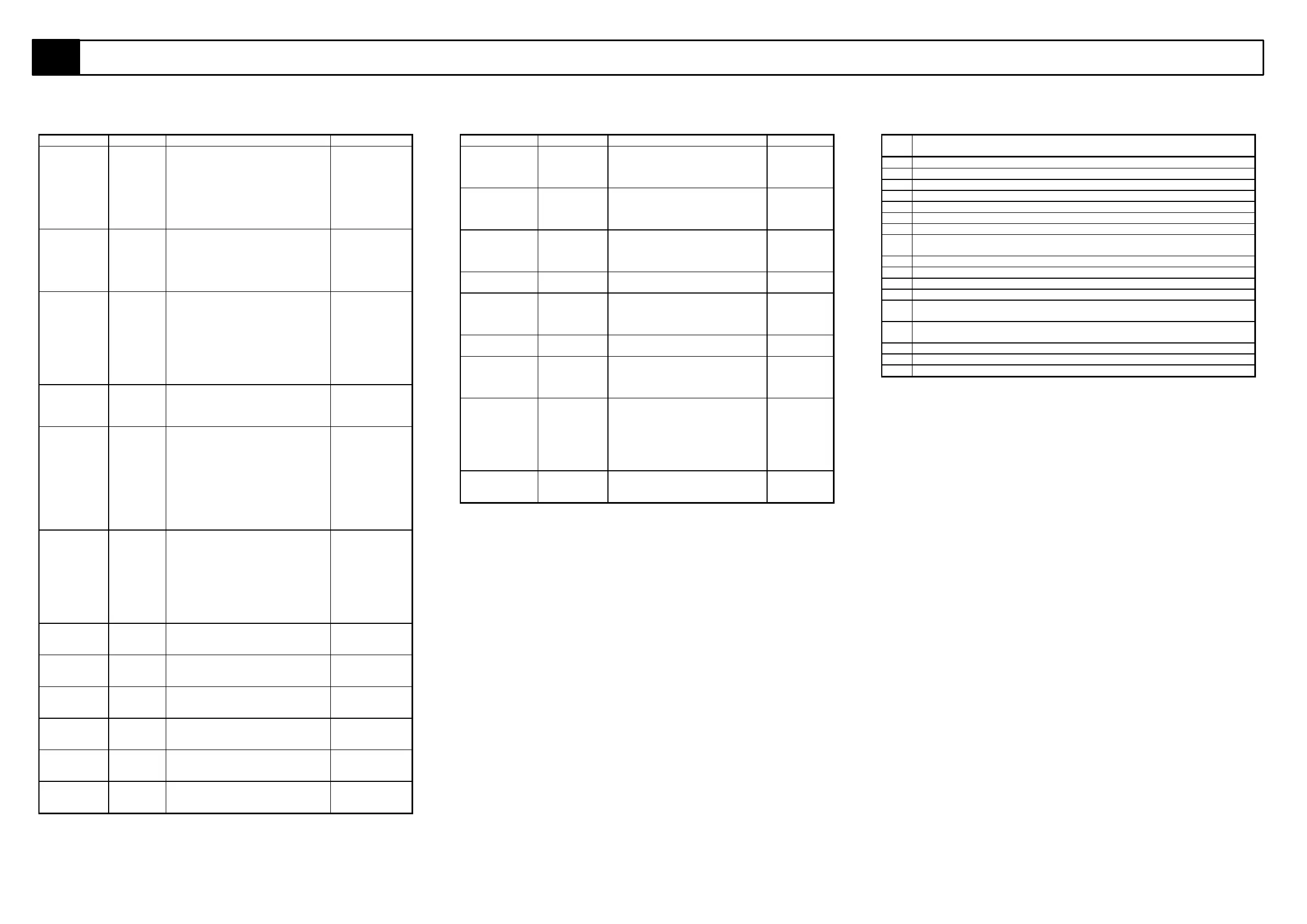
6.1 Electrical Schematic SERIAL NUMBERS: 1133 TO 1330
Table 6-1: Electrical Schematic Legend (Contd...)
REFERENCE NAME FUNCTION LOCATION
LS1,LS2,LS3
& LS4.
Outrigger
Limit
Switches.
Activated when the outriggers are
deployed and taking load. +24V
supply from the batteries is routed
through these four limit switches,
which are wired in series, to the
keyswitch and provides power to the
upper and lower control boxes for
operation of the boom functions.
On Outrigger
supports.
LS5 Slew cut-
out limit
switch.
This prevents slewing until the
second post is clear of the tow bar.
The normally closed contact is open
and the slew signal to pin 4 on the
controller is broken until the second
post is clear of the towbar.
On first post
under lower
boom.
MCU Motor
Control
Unit.
This controls the speed of the
electric motor. Using the upper
controls the motor speed varies with
the position of the control joystick.
Using the lower controls the motor
has different fixed speeds for the
various functions which are
programmed into the MCU using a
special calibrator.
Chasis
Subframe.
MOT 24V D.C.
Electric
Motor.
This motor is coupled to the
hydraulic pump which provides the
oil flow and pressure to operate the
various machine functions.
Chasis
Subframe.
RL1 Joystick
direction
relay.
This relay is energised when the
joystick is pushed foward. The
contacts close allowing +24V to be
fed into only one half of the contacts
on the selector switch. This then
allows only one of the two solenoids
on each function spool to be
energised thus allowing only one
direction of motion when the joystck
is pushed forward.
Upper Control
Box P.C.B.
RL2 Joystick
direction
relay.
This relay is energised when the
joystick is pulled backwards. The
contacts close and feed +24V to
opposite set of contacts on the
selector switch as RL1 does. This
then energises the opposite solenoid
for each function and provides
motion in the opposite direction
when the joystck is pulled back.
Upper Control
Box P.C.B.
SOL1 Solenoid Solenoid used for activating
hydraulic valve to slew in the right
direction
Back of first
post.
SOL2 Solenoid Solenoid used for activating
hydraulic valve to raise the first
boom.
Back of first
post.
SOL3 Solenoid Solenoid used for activating
hydraulic valve to raise the second
boom.
Back of first
post.
SOL4 Solenoid Solenoid used for activating
hydraulic valve to slew in the left
direction
Back of first
post.
SOL5 Solenoid Solenoid used for activating
hydraulic valve to lower the first
boom.
Back of first
post.
SOL6 Solenoid Solenoid used for activating
hydraulic valve to lower the second
boom.
Back of first
post.
REFERENCE NAME FUNCTION LOCATION
SW 1 Function
switch Lower
Boom.
Sends power to the lower lift
cylinder solenoid which diverts oil
to full bore or annular side of lower
lift cylinder.
Lower
control box.
SW 2 Function
switch Upper
Boom.
Sends power to the upper lift
cylinder solenoid which diverts oil
to full bore or annular side of upper
lift cylinder.
Lower
control box.
SW 3 Function
switch slew.
Sends power to the slew motor
control solenoid which diverts oil to
the left or right side of the slew
motor.
Lower
control box.
SW 4 Emergency
stop button.
Control circuit shut off. Lower
Control Box.
SW 5 Switch-
3 position
selector
Sends power to selected solenoid
valve (lower lift, upper lift, tele &
slew). Only one function can be
selected at any time.
Upper
Control Box.
SW 6 Emergency
stop button.
Control circuit shut off. Upper
Control Box.
SW 7 Switch,
Emergency
Override.
Provides emergency power when
power is cut to the upper controls
due to an outrigger limit switch de-
activating.
Upper
Control Box.
SW 8 Swith On/Off Allows +24V supply to feed upper
controls. Allows signals from tele
and lift functions to pass down to
the controller. Allows joystick
trigger signal to pass down do the
controller. (this switch is combined
in the same housing as SW7)
Upper
Control Box.
TS 1 Tilt Alarm.
(option)
This is a warning device that will
sound if the machine tilts at an
angle greater than 3 degrees
Chasis
Subframe.
MOTOR CONTROL UNIT (PIN LEGEND)
PIN
No.
DESCRIPTION
1 Battery Discharge Indicator (B.D.I.) output
2 Not used - sw8 - Switch 8
3 Not used - 10V supply
4 sw4 - Switch 4 (Speed 4: slew speed from lower controls - Factory set at 13%)
5 Not used - Not connected.
6 24V supply (Must be greater than 14V)
7 Not used - Not connected.
8 sw1 - Switch 1 (speed 1: Max. variable speed for upper and lower lift cylinders
from upper controls - Factory set at 90%)
9 Not used - Not connected.
10 Not used - Not connected.
11 Not used - Not connected.
12 sw3 - Switch 3 (Speed 3: Boom speeds from lower controls - Factory set at 45%)
13 sw2 - Switch 2 (Speed 2: Max variable slewing speed from upper controls -
Factory set at 40%)
14 Accelerator (3.5V - 0V) - Input from joystick to vary motor speed from upper
controls.
15 Not used - Not connected.
16 Not used - Not connected.
17 Not used - Not connected.