EasyManuals Logo

Vacon 20 SERIES User Manual

Vacon 20 SERIES
72 pages
To Next Page IconTo Next Page
To Previous Page IconTo Previous Page
Page #57 background imageLoading...
Page #57 background image
Parameter description vacon • 54
Service support: find your nearest Vacon service center at www.vacon.com
3
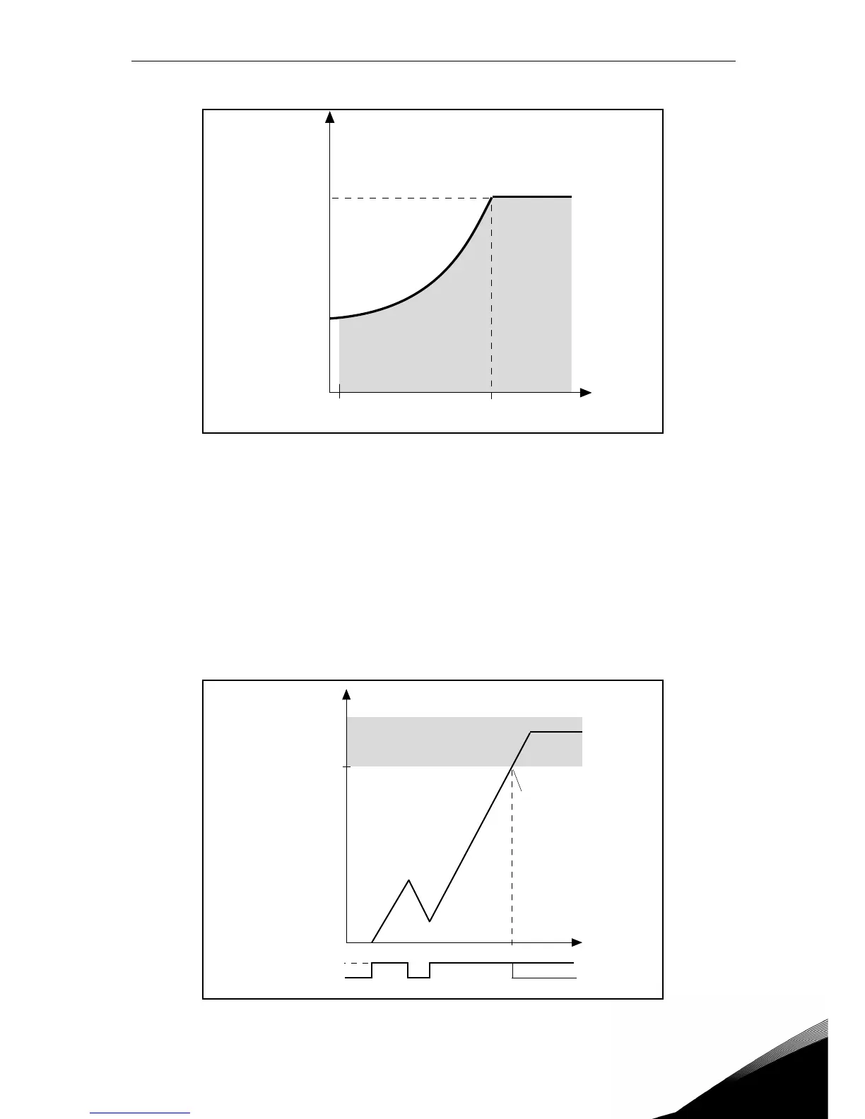
Figure 10. Underload characteristic settings.
P10.7 UNDERLOAD FAULT: ZERO FREQUENCY LOAD
P10.8 UNDERLOAD FAULT: TIME LIMIT
Definition of minimum load at nominal and zero speed zero. Fault condition delay. This time
can be set between 1.0 and 300.0 s.
This is the maximum time allowed for an underload state to exist. An internal up/down counter
counts the accumulated underload time. If the underload counter value goes above this limit
the protection will cause a trip according to parameter P10.5). If the drive is stopped the un-
derload counter is reset to zero.
Figure 11. Underload time counter.
Par.
P10.6
Par.
P10.7
f
5 Hz
Underload area
Torque
Fieldweakening
point
Par. P10.8
Trip area
Time
Underload time counter
Underload•
No underl.
Trip/warning
par. P10.5

Questions and Answers:

Question and Answer IconNeed help?

Do you have a question about the Vacon 20 SERIES and is the answer not in the manual?

Vacon 20 SERIES Specifications

General IconGeneral
Output Voltage0 to Input Voltage
Storage Temperature-40°C to +70°C
DimensionsVaries by model
WeightVaries by model
Power Range0.25 kW to 18.5 kW
Voltage Range200 V to 480 V
Control MethodSensorless vector control
Protection ClassIP20
Ambient Temperature-10°C to +50°C
Communication OptionsModbus, CANopen
EMC FilterIntegrated
STO (Safe Torque Off)Yes
Input Voltage208-240 V, 380-480 V
Protection FeaturesOvervoltage, Undervoltage, Overcurrent, Overtemperature
Operating Temperature-10°C to +50°C
Humidity5% to 95% non-condensing

Related product manuals