shaft synchronization operation vacon • 89
24-hour support +358 (0)40 837 1150 • Email: vacon@vacon.com
8
Engineering distance unit is defined by the user.
The Kinematic ratio is to be set up for the master (P2.9.1.1 … P2.9.1.4) and the follower drive
(P2.9.2.1 … P2.9.2.4). This describes the physical relationship between the master and follower
drive.
Synchronization Commands:
Can be performed by digital inputs (see P2.2.5.20, P2.2.5.21) or from fieldbus interface (see table 39)
Shaft synchronization mode has to be enabled to accept these commands.
Note: When Shaft synchronization is disabled the normal Multi-purpose speed control is active.
Sync Mode bit 1 Sync Mode bit 0 Action
0 0 Release synchronization
0 1 Engage synchronization
1 0 Use reference speed given
from selected reference place.
1 1 Freeze follower speed. Only
possible when synchronization
is engaged to master speed.
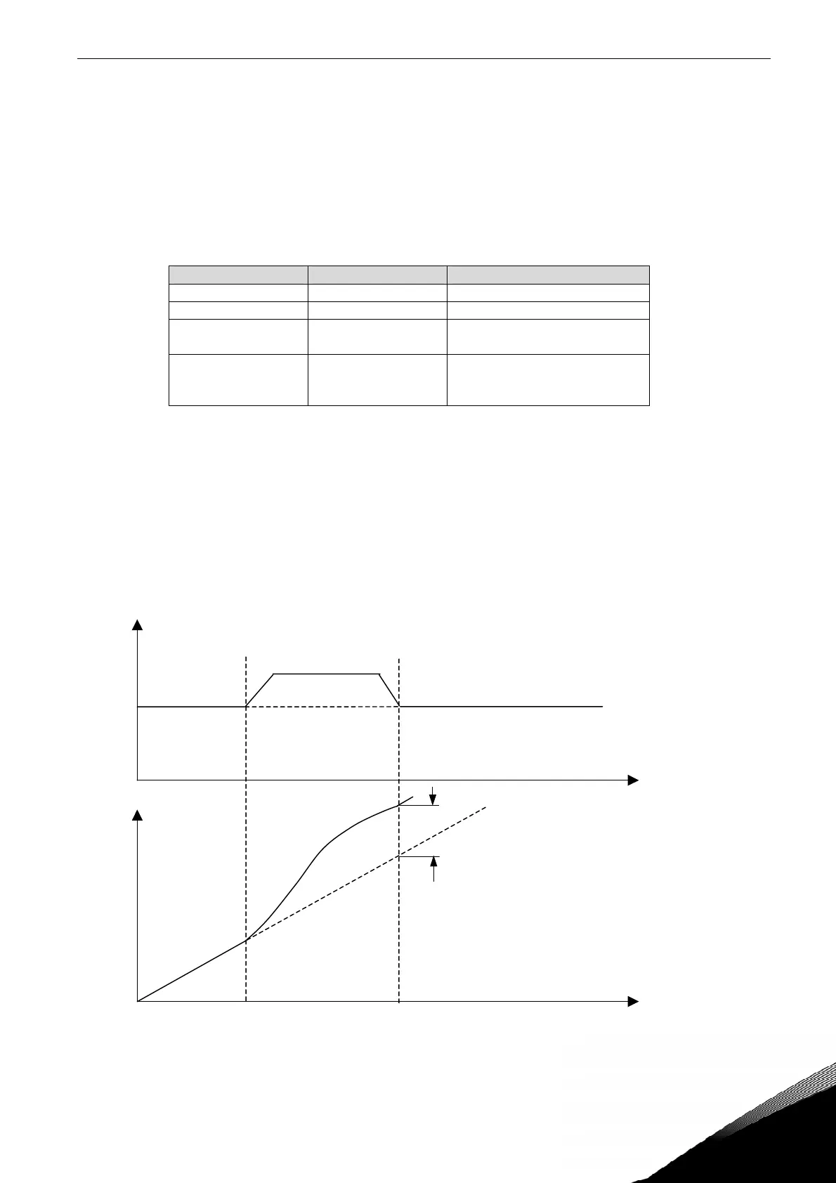
Phasing Commands:
Shaft synchronization mode has to be enabled and Sync mode B0=1 to accept these commands.
The phasing command is for exact position adjustment in user units of follower. It can be executed
when follower is in standstill or when running synchronized. The control bit BO has to be on to
accept phasing commands.
The maximum frequency is the speed limit during phasing.
Acceleration/Deceleration during phasing command is same as for engage/release synchronization
See P2.9.2.8 Sync Acceleration.
Velocity
time
phase velocity
master velocity
Position
time
Master pos “seen” by
follower
Phasing
distance