28 • vacon shaft synchronization application – parameter lists
Tel. +358 (0)201 2121 • Fax +358 (0)201 212 205
6
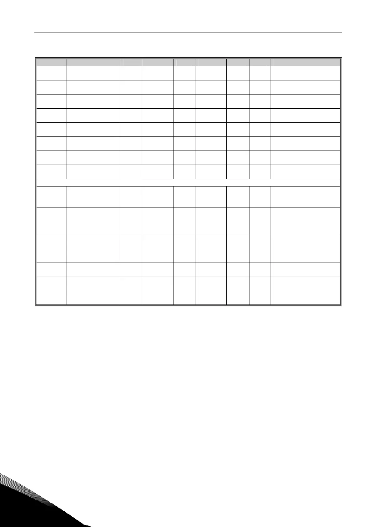
6.8 Fieldbus parameters (Control Keypad: Menu M2 G2.7)
Code Parameter Min Max Unit Default Cust ID Note
P2.7.1
Fieldbus data out 1
selection
0 10000 0
852
Choose monitoring data
with parameter ID
P2.7.2
Fieldbus data out 2
selection
0 10000 0
853
Choose monitoring data
with parameter ID
P2.7.3
Fieldbus data out 3
selection
0 10000 1703
854
Choose monitoring data
with parameter ID
P2.7.4
Fieldbus data out 4
selection
0 10000 4
855
Choose monitoring data
with parameter ID
P2.7.5
Fieldbus data out 5
selection
0 10000 5
856
Choose monitoring data
with parameter ID
P2.7.6
Fieldbus data out 6
selection
0 10000 6
857
Choose monitoring data
with parameter ID
P2.7.7
Fieldbus data out 7
selection
0 10000 7
858
Choose monitoring data
with parameter ID
P2.7.8
Fieldbus data out 8
selection
0 10000 37
859
Choose monitoring data
with parameter ID
SHAFT SYNCHRONIZATION SPECIFIC PARAMETERS (See separate description)
P2.7.9
Fieldbus data out
1_2 selection
0 10000 1702
1740
Choose 32-bit monitoring
data with parameter ID.
See separate description.
P2.7.10
Synch. ratio register
selection
0 7 0
1741
Selection of PD in chan-
nels for ratio register.
Occupies 2 PD in
channels !
P2.7.11
Synch. control
register selection
0 8 1
1742
Selection of PD in chan-
nel for synchronization
control register. See
table 39.
P2.7.12
Torque reference
selection
0 8 6
1680
Select PD in channel for
Torque reference
P2.7.13 Free signal selection 0 8 7
1681
Select PD in channel for
Free Signal. Can be used
for Torque or Current
limit. See G2.2.4.
Table 21. Fieldbus parameters