26 • vacon shaft synchronization application – parameter lists
Tel. +358 (0)201 2121 • Fax +358 (0)201 212 205
6
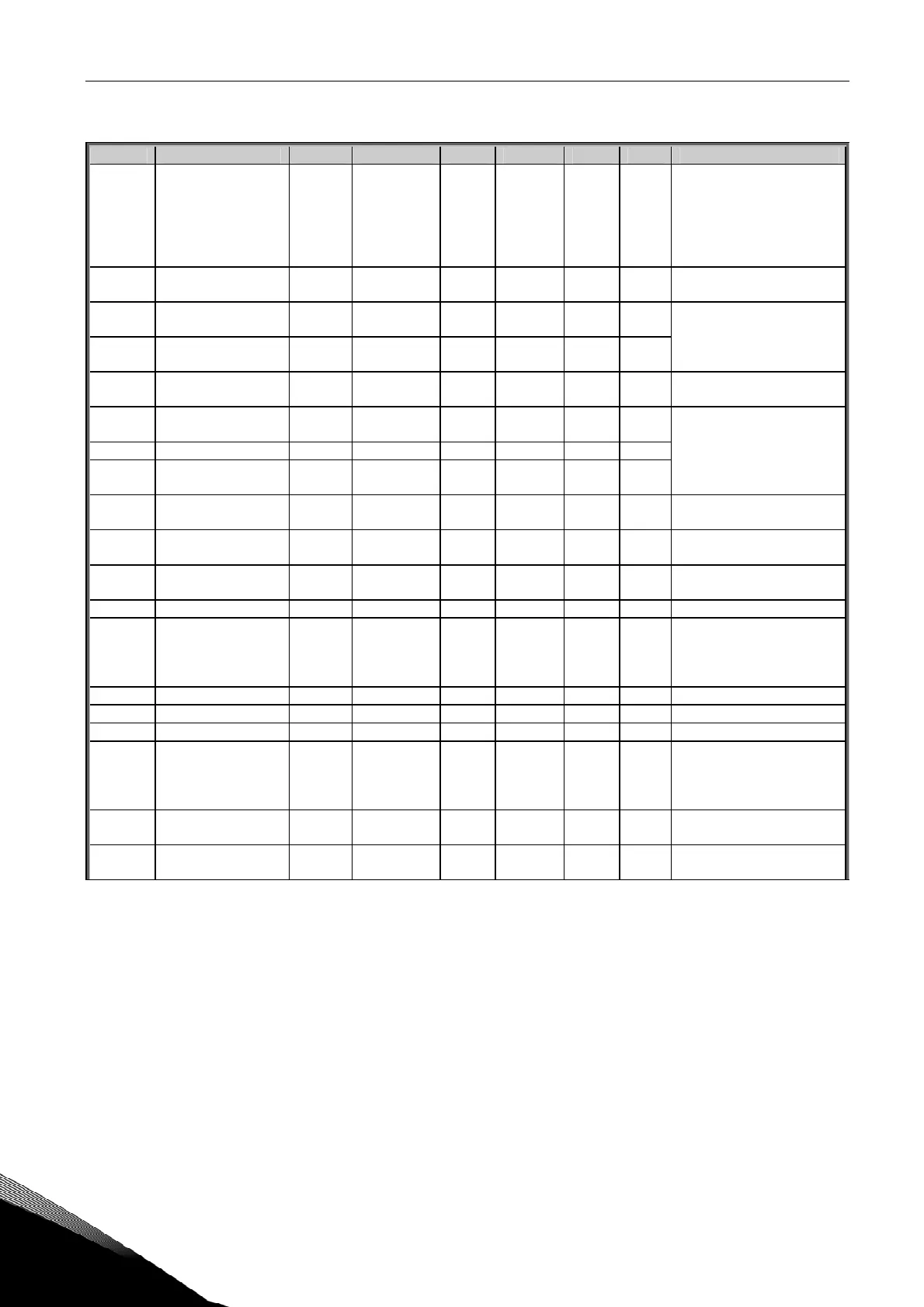
6.7 Protections (Control keypad: Menu M2 G2.6)
Code Parameter Min Max Unit Default Cust ID Note
P2.6.1
Response to 4mA
reference fault
0 5 0
700
0=No response
1=Warning
2=Warning+Prev. Freq.
3=Wrng+PresetFreq 2.7.2
4=Fault,stop acc. to 2.4.7
5=Fault,stop by coasting
P2.6.2
4mA reference fault
frequency
0,00 Par. 2.1.2 Hz 0,00
728
P2.6.3
Response to external
fault
0 3 2
701
P2.6.4
Input phase
supervision
0 3 0
730
0=No response
1=Warning
2=Fault,stop acc. to 2.4.7
3=Fault,stop by coasting
P2.6.5
Response to
undervoltage fault
0 1 0
727
0=Fault stored in history
1=Fault not stored
P2.6.6
Output phase
supervision
0 3 2
702
P2.6.7 Earth fault protection 0 3 2 703
P2.6.8
Thermal protection
of the motor
0 3 2
704
0=No response
1=Warning
2=Fault,stop acc. to 2.4.7
3=Fault,stop by coasting
P2.6.9
Motor ambient
temperature factor
–100,0 100,0 % 0,0
705
P2.6.10
Motor cooling factor
at zero speed
0,0 150,0 % 40,0
706
P2.6.11
Motor thermal time
constant
1 200 min 45
707
P2.6.12 Motor duty cycle 0 100 % 100 708
P2.6.13 Stall protection 0 3 0
709
0=No response
1=Warning
2=Fault,stop acc. to 2.4.7
3=Fault,stop by coasting
P2.6.14 Stall current 0,1 I
nMotor
x 2 A I
L
710
P2.6.15 Stall time limit 1,00 120,00 s 15,00 711
P2.6.16 Stall frequency limit 1,0 Par. 2.1.2 Hz 25,0 712
P2.6.17
Response to
thermistor fault
0 3 2
732
0=No response
1=Warning
2=Fault,stop acc. to 2.4.7
3=Fault,stop by coasting
P2.6.18
Response to
fieldbus fault
0 3 2
733 See P2.6.17
P2.6.19
Response to slot
fault
0 3 2
734 See P2.6.17