control i/o vacon • 7
24-hour support +358 (0)40 837 1150 • Email: vacon@vacon.com
2
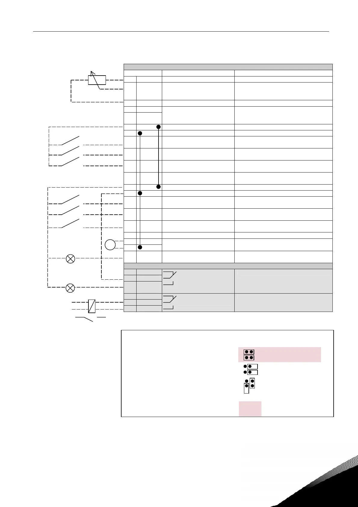
umper bloc
3:
CMA and CMB grounding
CMB connected to GND
CMA connected to GND
CMB isolated from GND
CMA isolated from GND
CMB and CMA
internally connected together,
isolated from GND
= Factory default
2. CONTROL I/O
OPT-A1
Terminal Signal Description
1 +10V
ref
Reference output Voltage for potentiometer, etc.
2 AI1+ Analogue input, voltage range
0—10V DC
Voltage input frequency reference
3 AI1- I/O Ground Ground for reference and controls
4 AI2+
5 AI2-
Analogue input, current range
0—20mA
Current input frequency reference
6 +24V Control voltage output Voltage for switches, etc. max 0.1 A
7 GND I/O ground Ground for reference and controls
8 DIN1 Start forward
(programmable)
Contact closed = start forward
9 DIN2 Start reverse
(programmable)
Contact closed = start reverse
10 DIN3 Shaft Synchronization Enable
(programmable)
Contact closed = Enabled
11 CMA
Common for DIN 1—DIN 3 Connect to GND or +24V
12 +24V Control voltage output Voltage for switches (see #6)
13 GND I/O ground Ground for reference and controls
14 DIN4 Synch. Mode BIT0
(programmable)
Contact closed = Engage Synchronization
15 DIN5 Synch. Mode BIT1
(programmable)
Contact closed = Freeze follower speed
16 DIN6 Free
(programmable)
Programmable
17 CMB Common for DIN4—DIN6 Connect to GND or +24V
18 AOA1+
19 AOA1-
Output frequency
Analogue output
Programmable
Range 0—20 mA/R
L
, max. 500Ω
20 DOA1 Digital output
READY
Programmable
Open collector, I≤50mA, U≤48 VDC
OPT-A2
21 RO1
22 RO1
23 RO1
Relay output 1
RUN
Programmable
24 RO2
25 RO2
26 RO2
Relay output 2
FAULT
Programmable
Table 1. Shaft Synchronization application default I/O configuration and
connection example.
Note: See jumper selections below.
More information in the product's
User's Manual.
READY
220
VAC
RUN
mA
Reference potentiometer,
1…10 kΩ