90 • vacon shaft synchronization operation
Tel. +358 (0)201 2121 • Fax +358 (0)201 212 205
8
Change of gear ratio during run:
The ratio of the follower to the master speed and position can be dynamically changed by a ramped,
high resolution ratio control. Ratio can be changed by P2.9.2.9 from keypad.
If fieldbus control is used better use the 2 process datas selected by P2.7.10.
See Figure 36.
In I/O control the ratio can be changed by P2.9.2.11 dynamically with the trim +/- inputs connected to
digital inputs selected by P2.2.5.22 and P2.2.5.23.
Then the ratio is temporarily changed when the trim input is active.
Function is useful for changing of the gear ratio during running. See Figure 36.
Output signal for diagnostics:
Digital or relay outputs include a flag to signal changing value of the ratio and a flag to signal that
space synchronization has been achieved.
The Ratio changing output is set whenever a change in the ratio is requested and it remains on until
the ramp has reached the required value.
The Synchronization engaged output is set at the end of execution of the Engage synchronization
command, after the follower has been brought to master speed x ratio and space control loop is
activated. The Synchronization engaged output is cleared whenever a Release synchronization
command is issued or whenever a Freeze command is issued.
The Synchronization engaged output is also cleared whenever a Drive stop is requested or a fault
occurs.
8.1 Shaft Synchronization fieldbus interface
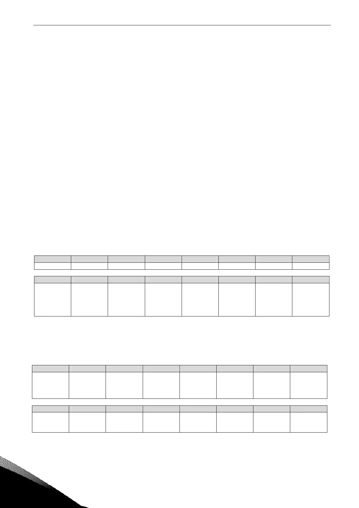
Control register mapping is shown in Table 40. (Process data for control selected by P2.7.11)
Bit 15 Bit 14 Bit 13 Bit 12 Bit 11 Bit 10 Bit 9 Bit 8
Enable Synch Reserved Reserved Reserved Reserved Reserved Reserved Reserved
Bit 7 Bit 6 Bit 5 Bit 4 Bit 3 Bit 2 Bit 1 Bit 0
Reserved Reserved Reserved Negative
Phasing
Positive
Phasing
Enable Sync
sequencer
(always set
this bit to 1)
Sync mode
bit 1 (Ramp
to reference
speed)
Sync mode
bit 0 (Engage
/release
synchro-
nization
Table 40. Shaft synchronization control register
The map of the status register is shown in Table 41. Status register contains additional detailed
information on the internal operation of the synchronization sequencer that is reserved for future
use on the fieldbus interface. The status bits significant for the existing control interface are
highlighted in bold characters.
Bit 15 Bit 14 Bit 13 Bit 12 Bit 11 Bit 10 Bit 9 Bit 8
Shaft synch.
enabled
Feed forward
enabled
Position
error
enabled
Position loop
active
Ratio
changing
PID regulator
enabed
PID Integral
action
enabled
PID
derivative
action
enabled
Bit 7 Bit 6 Bit 5 Bit 4 Bit 3 Bit 2 Bit 1 Bit 0
Reserved Reserved Reserved Reserved Speed frozen Synchro-
nization
reached
Releasing
synchro-
nization
Engaging
synchro-
nization
Table 41. Shaft synchronization status register