shaft synchronization application – parameter lists vacon • 19
24-hour support +358 (0)40 837 1150 • Email: vacon@vacon.com
6
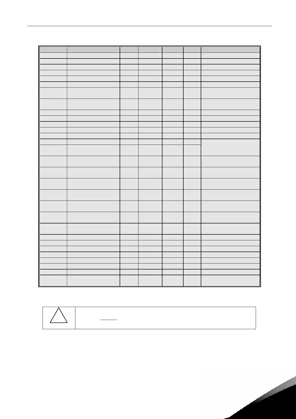
6.4.3 Digital output signals (Control keypad: Menu M2 G2.3.3)
Code Parameter Min Default Cust ID Note
P2.3.3.1 Ready 0 A.1 432
P2.3.3.2 Run 0 B.1 433
P2.3.3.3 Fault 0 B.2 434
P2.3.3.4 Inverted fault 0 0.1 435
P2.3.3.5 Warning 0 0.1 436
P2.3.3.6 External fault 0 0.1 437
P2.3.3.7
Reference
fault/warning
0 0.1 438
P2.3.3.8
Overtemperature
warning
0 0.1 439
P2.3.3.9 Reverse 0 0.1 440
P2.3.3.10 Unrequested direction 0 0.1 441
P2.3.3.11 At speed 0 0.1 442
P2.3.3.12 Jogging speed 0 0.1 443
P2.3.3.13 External control place 0 0.1 444
P2.3.3.14 External brake control 0 0.1 445
P2.3.3.15
External brake control,
inverted
0 0.1 446
See explanations on page
53.
P2.3.3.16
Output frequency limit
1 supervision
0 0.1 447
P2.3.3.17
Output frequency limit
2 supervision
0 0.1 448
P2.3.3.18
Reference limit
supervision
0 0.1 449
P2.3.3.19
Temperature limit
supervision
0 0.1 450
P2.3.3.20
Torque limit
supervision
0 0.1 451
P2.3.3.21
Motor thermal
protection
0 0.1 452
P2.3.3.22
Motor regulator
activation
0 0.1 454
P2.3.3.23 Fieldbus input data 1 0 0.1 455
P2.3.3.24 Fieldbus input data 2 0 0.1 456
P2.3.3.25 Fieldbus input data 3 0 0.1 457
P2.3.3.26 Fieldbus input data 4 0 0.1 169
P2.3.3.27 Fieldbus input data 5 0 0.1 170
P2.3.3.28 SynchronEngaged 0 0.1 1720
P2.3.3.29 Ratio changing 0 0.1 1721
P2.3.3.30 External Brake Opened 0 0.1 1722
Indication for mechanical
brake fully open
Table 11. Digital output signals, G2.3.3
!
WARNING
Be ABSOLUTELY sure not to connect two functions to one and
same output
in order to avoid function overruns and to ensure
flawless operation.