68 • vacon description of parameters
Tel. +358 (0)201 2121 • Fax +358 (0)201 212 205
7
f
f
n
Par.
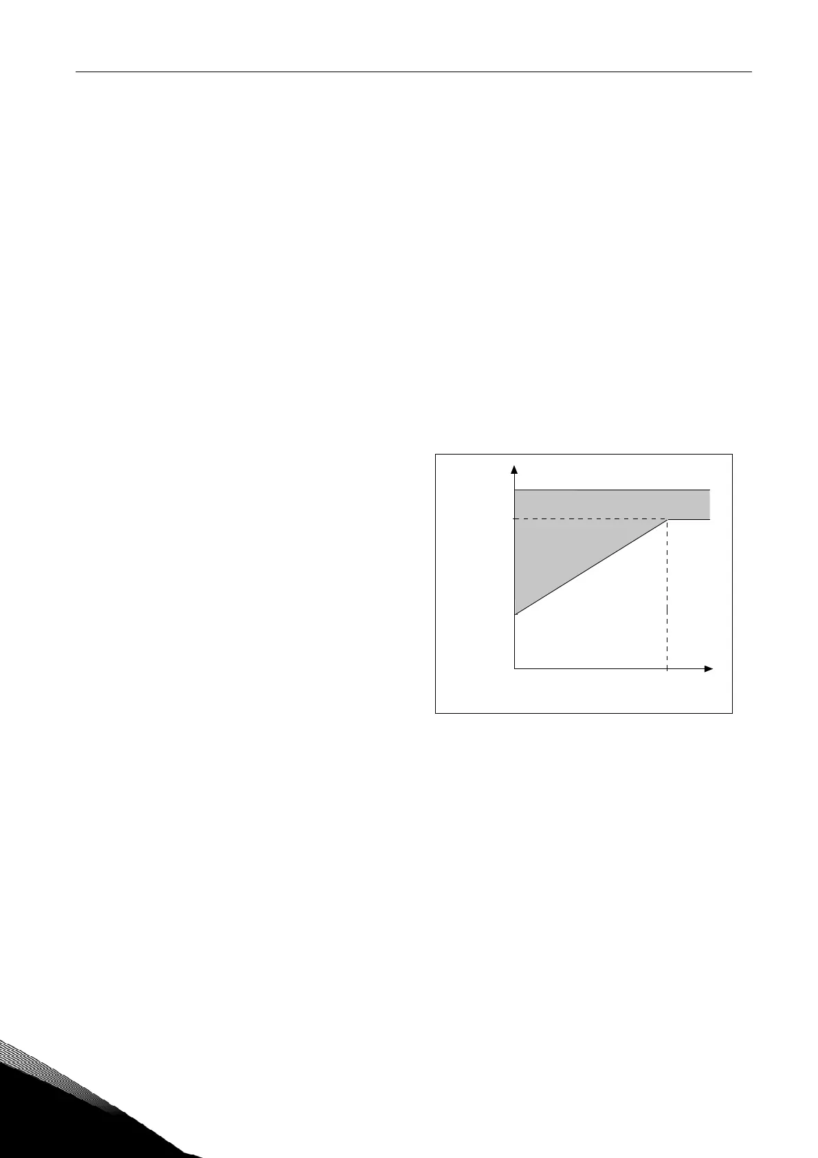
ID706=40%
0
NX12k62
I
T
100%
Overload area
P
cooling
705 Motor thermal protection: Motor ambient temp. factor
(2.6.9)
The factor can be set between -100.0%—100.0%. See chapter 9.2.
706 Motor thermal protection: Motor cooling factor at zero speed
(2.6.10)
The current can be set between 0—150.0% x I
nMotor
. This parameter sets the value for
thermal current at zero frequency. See Figure 23.
The default value is set assuming that there is no external fan cooling the motor. If an
external fan is used this parameter can be set to 90% (or even higher).
Note: The value is set as a percentage of the motor name plate data, par. ID113
(Nominal current of motor), not the drive's nominal output current. The motor's nominal
current is the current that the motor can withstand in direct on-line use without being
overheated.
If you change the parameter Nominal current of motor, this parameter is automatically
restored to the default value.
Setting this parameter does not affect the maximum output current of the drive which is
determined by parameter ID107 alone. See chapter 9.2.
Figure 23. Motor thermal current I
T
curve
707 Motor thermal protection: Time constant
(2.6.11)
This time can be set between 1 and 200 minutes.
This is the thermal time constant of the motor. The bigger the motor, the bigger the time
constant. The time constant is the time within which the calculated thermal stage has
reached 63% of its final value.
The motor thermal time is specific to the motor design and it varies between different
motor manufacturers.
If the motor's t6–time (t6 is the time in seconds the motor can safely operate at six times
the rated current) is known (given by the motor manufacturer) the time constant
parameter can be set basing on it. As a rule of thumb, the motor thermal time constant
in minutes equals to 2xt6. If the drive is in stop stage the time constant is internally
increased to three times the set parameter value. The cooling in the stop stage is based
on convection and the time constant is increased. See also Figure 24.