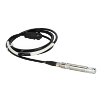
Ceilometer CT25K
CT25K-U059en-2.1 User’s Guide
91
6. Check the status message.
All the VOLTAGES, RECEIVER and TRANSMITTER values are within
predefined limits if no asterisks (*) appear. An asterisk in front of a
variable indicates that an alarm or warning limit of that variable is
exceeded. In the status example above, the battery voltage is too low.
Check the TEMPERATURES. The OUTSIDE temperature should be close
to the environment temperature. The CPU, LASER and LENS temperatures
are typically 10-15 degrees higher than the OUTSIDE temperature.
Compare the ANGLE. If the ceilometer is in a vertical position (i.e.
pointing upwards) the ANGLE should be -2 ... +2 degrees.
7. Check the message line operation.
Give the commands:
SET MESSAGE PORT MAINTENANCE ↵
CLOSE↵
The following lines should appear (example: Msg 1):
(CTA2010J↵
00 ///// ///// ///// 00000200↵
L↵
Reading instructions for the second line, identical in all messages:
Message 0 0 ///// ///// /////
FEDCBA98↵
Position 1 2 3 4 5 6
Position 1: 0 indicates that no cloud layers are detected
Position 2: 0 indicates that there are no warnings or alarms, W indicates a
warning and A indicates an alarm.
Position 3 .. 5: ///// indicates no cloud heights
Position 6: Alarm (A), Warning (W), and internal status information.
Each character is a hexadecimal representation of four bits,
altogether 32 bits, with the following breakdown.
Interpretation as follows:
F: (8000 0000) Laser temperature shut-off (A)
(4000 0000) Laser failure (A)
(2000 0000) Receiver failure (A)
(1000 0000) Voltage failure (A)
E: (0800 0000) (spare) (A)
(0400 0000) (spare) (A)
(0200 0000) (spare) (A)
(0100 0000) (spare) (A)
 Loading...


