Ceilometer CT25K
CT25K-U059en-2.1 User’s Guide
69
Output voltages:
Signal name Acceptable
Range (V)
Nominal
current(A)
+5V 5.0 .. 5.8 0.15
-5V -5.8 .. –5.0 0.05
+5VDISC 5.0 .. 5.8 0.45
+18V 16.0 .. 18.5 0.010
+12V 12.0 .. 13.5 0.1
-12V -13.5 .. -11.5 0.1
+65V 60 .. 90 0.015
+13VR 12.0 .. 14.0 0.02
-13VR -14.0 .. -12.0 0.01
+5VR 4.8 .. 5.2 0.06
-5VR -5.8 .. -4.5 0.07
+400VR 360 .. 425 0.003
VBAT 11.5 .. 16.5 0 .. 0.5
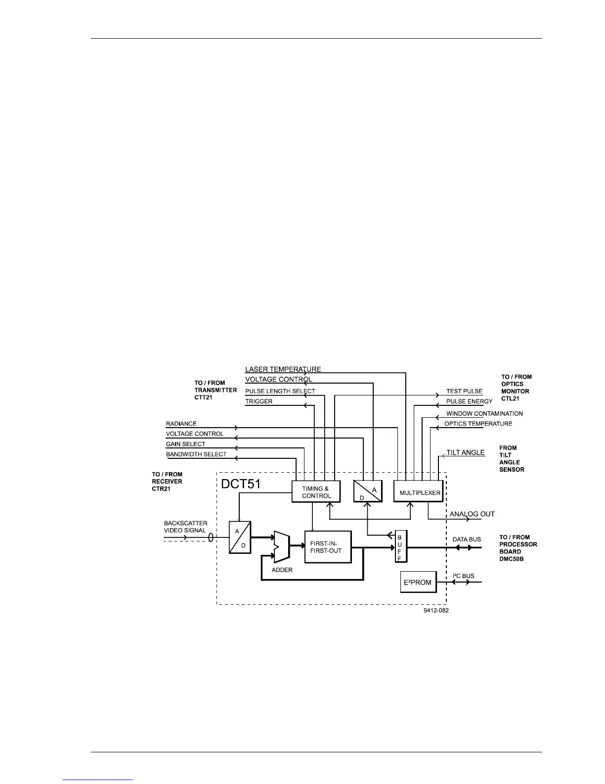
5.3.8 Ceilometer Interface Board DCT51
Figure 5-13 DCT51 Block Diagram
The Ceilometer Interface Board DCT51 together with the Processor Board
DMC50B are the main components in obtaining the LIDAR backscatter
signal, controlling the laser transmitter as well as in real-time processing of
the backscatter signal from the receiver as described in Paragraph 5.2.2.
Additionally the ceilometer interface board DCT51 contains special circuitry
for the timing of all activities and a very fast flash A-to-D Converter. The