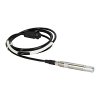
Ceilometer CT25K
User’s Guide CT25K-U059en-2.1
80
4-pin connector:
This connector carries telephone line audio signals for special
applications, and SHALL NOT BE CONNECTED when the DMX50 is
to be used over public telephone lines.
6-pin connector:
For line connection. The attached modular telephone cable connector
shall be connected to this jack.
5.3.16 DMX611 ANet Interface (Option)
The DMX611 serves as an interface between the CT25K and Vaisala
proprietary Anet and Inet busses.
Figure 5-21 DMX611 Block Diagram
LED indicators
The front panel has four LEDs. They have labels RTR, ISI, RxD and TxD.
The definitions of these LEDs, during normal operation, are as follows:
RTR Router life. This LED will flash at one flash per second, indicating
the Router portion of the DMX611 is actively executing code.
ISI iSi life. This LED will flash at two flashes per second, indicating the
iSi portion of the DMX611 is actively executing code.
RxD This LED will flash as the DMX611 receives data from the CT25K
(or from any device attached to the front panel RxD input).
 Loading...


