Ceilometer CT25K
User’s Guide CT25K-U059en-2.1
58
thus the resulting distortion is visible to the software in the raw measurement
profile, and this is iteratively kept within limits.
5.2.3 Internal Monitoring and Control
All essential subassembly functions are monitored continuously to ensure
measurement accuracy and reliability. Temperature, laser performance etc. is
measured by sensors and transferred to Processor Board DMC50B, converted
from analog to digital by its Monitor A-to-D Converter and further analyzed
by the processor software.
Warning and Alarm limits are defined in software through parameter settings.
In case a malfunction has been detected, i.e. the limits have been exceeded,
the software sends warning and alarm messages which can be seen by the
STATUS message (Paragraph 4.4.11)
5.3 Module Descriptions
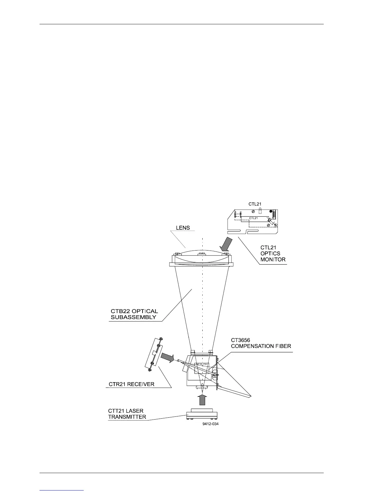
5.3.1 Optical Subassembly CTB22
Figure 5-5 Optical Subassembly CTB22 with Optics Monitor,
Transmitter and Receiver Subassemblies