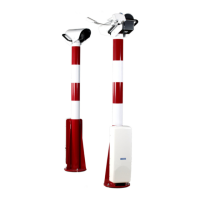
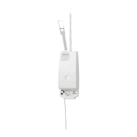
Ceilometer CT25K
CT25K-U059en-2.1 User’s Guide
19
3. START UP
3.1 Start up procedure
Open the unit door; the key is included in the delivery. Make a visual check of
the internal connectors, subassemblies, etc. Figure 3-1 describes the switches
and LEDs needed to complete the start up procedure.
1. Turn the main circuit breaker F1 to "OFF" position.
2. Plug in the line supply cable to connector J2 after checking the voltage of
the power supply cable connector.
3. Turn the Main Circuit Breaker F1 and the Battery Switch to the "ON"
position. After initialization routines the following shall happen (LED =
Light Emitting Diode):
DC Converter DPS52 LED D2 stable green
LED D1 blinking yellow
In case the built-in battery is deeply discharged it may take hours before
LED D2 goes on.
4. Processor Board DMC50B LED STATUS blinking at regular intervals
(1 sec.)
5. Ceilometer Interface Board DCT51 green LED D4 goes on during the
laser pulse train for about 12 seconds and is repeated according to the
configuration in question. After power-up, it may take a couple of minutes
before the unit starts normal operation.
If LEDs operate in a different way than described above, the unit may need
service or maintenance. Refer to Chapter 7 Troubleshooting.
 Loading...


