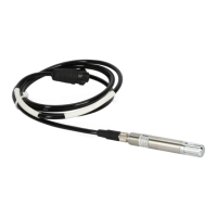
Ceilometer CT25K
User’s Guide CT25K-U059en-2.1
2
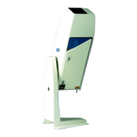
Ceilometer CT25K consists of three main parts (Figure 1-1):
1. Measurement Unit including
- Optical Subassembly CTB22
- Laser transmitter CTT21
- Receiver CTR21
- Optics Monitor CTL21
- Frame DMF51 including
- Processor Board DMC50B
- DC Converter DPS52
- Ceilometer Interface Board DCT51
- Modem (optional)
- Line and Power Interface Subassembly CTP241
- No-Break Battery
- Internal Heaters Subassembly CT25039
- Tilt Angle Sensor CT3675
- Internal Cables etc.
2. Shield including
- Built-in Window Conditioner CT2614/CT2688 (warm air blower)
options - 220...240 VAC (CT2614)
- 100...115 VAC (CT2688)
3. Pedestal
- Metal pedestal CT25106 is standard. For off-shore applications it is
recommended to use fiberglass pedestal CT2665.
The complete delivery also includes mating cables with connectors for power
and communication, installation hardware, an Allen key, a triangle key for the
Measurement Unit door and this CT25K User’s Guide.
In addition, the following options may be included in the delivery:
- Maintenance Terminal (Palmtop computer) PSION3
- connected to Measurement Unit at the external connector J4 via RS-
232 interface
- Termination Boxes (2) for Line Power CT3709 (external connector J2)
and Communication Cable CT3707 (external connector J3) connections
- Tropics Window CT35043 on Measurement Unit instead of Standard
Window to protect the laser from direct sun radiation.
- Optical Termination Hood CT25184 for indoor service use
 Loading...


