Ceilometer CT25K
CT25K-U059en-2.1 User’s Guide
15
As these advantages are partly contradictory and cannot or need not all be
realized, the user must decide the final installation direction. In doing so, the
following must be observed:
NOTE
Unless a tropics window is used, the unit must never be
directed so that the sun shines directly into the optics,
because the lens will focus all radiation into a very hot
spot.
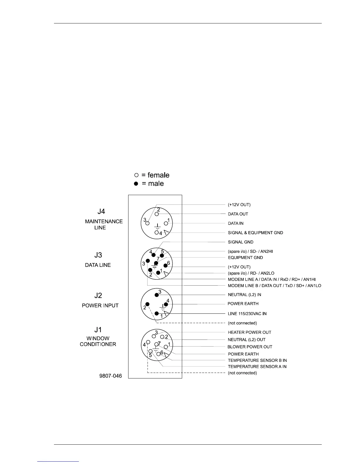
2.5 Cable Connections
All external connectors to the Measurement Unit are located at the bottom left
edge as seen from the door direction. Figure 2-5 shows the external
connectors J1, J2, J3 and J4.
Figure 2-5 External Connectors (bottom view)
• The Window Conditioner (warm air blower) mounted in the Shield is
permanently connected to J1.
• Line Power input is connected to J2.