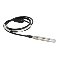
Ceilometer CT25K
CT25K-U059en-2.1 User’s Guide
5
Standard Character Frame: 1 Start Bit
7 Data Bits
Even Parity
1 Stop Bit
Standard Character Code: USASCII
Pin Connections 1 RD- / AN2Lo
2 Modem Lead A / RxD / RD+ / AN1Hi
3 Modem Lead B / TxD / SD+ / AN1Lo
4 Signal Ground
5 SD- / AN2Hi
6 +12 V DC supply (200 mA max for 1
hour, 100 mA continuous, for external
equipment)
Modem circuits are non-polar and symmetrical. All modem circuits are
electrically floating to overvoltage protection rating (300V-500V).
Overvoltage Protection in each circuit:
Primary Noble Gas Surge Arrester
Secondary VDRs, Transient Zener Diodes
or normal Diodes
Figure 1-2 Data Line Connection Options
 Loading...


