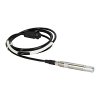
Ceilometer CT25K
User’s Guide CT25K-U059en-2.1
112
2. Detach the Ribbon Cable Connector of the Receiver from the connector J11
at the DMF51 Board Frame. Refer to Figure 8-1.
3. Detach the Coaxial Cable from the DCT51 front panel.
4. Loosen the CTR21 Receiver attachment ring (See Figure 8-5) using a 2.5
mm hexagon key as a lever; there are holes in the attachment ring for that
purpose. If the Receiver begins to move along, stop it from rotating by
hand. The photodiode has been centered at the factory - do not apply
force to the Receiver because this may disturb the centering.
5. Take the receiver in your hand and detach the Coaxial Cable from the
receiver.
6. If the Coaxial Cable is found defective, replace with a new one (refer to the
following paragraph 8.5.3.2 Replacement.)
8.5.3.2 Replacement
To replace the Coaxial Cable (Note Paragraph 8.3 Start up procedure for
replacement):
1. Attach the new Coaxial Cable to connector J2 of the receiver. Note the
marked ends of the cable.
2. Take the Receiver CTR21 in your hand and set it in place. The ribbon and
coaxial cables come out from the back side. Rotate the attachment ring
(Figure 8-5) first by hand and then tighten it using a 2.5 mm hexagon key
as a lever. If the receiver begins to move along, carefully stop it by hand
from rotating. Do not apply force to the receiver itself because it may
disturb the centering.
Check the receiver correct position, that is, the long edges of the receiver
case are approx. horizontal. If this is not the case, loosen the attachment
ring first, then correct the receiver position and fasten as described above.
3. Plug the Compensation Fiber into the receiver and tighten the screw
(marked Fibre attachment) with a 1.5 mm hexagon key.
4. Attach the Coaxial Cable to the connector J1 at the front panel of DCT51.
5. Attach the ribbon cable connector to the DMF51 Card Cage to connector
J11. Refer to Figure 8-1.
6. Connect the Power Cable and the Maintenance Terminal. Turn the power
on. No parameter settings are needed. Verify that the Ceilometer is
operating properly.
 Loading...


