Ceilometer CT25K
User’s Guide CT25K-U059en-2.1
72
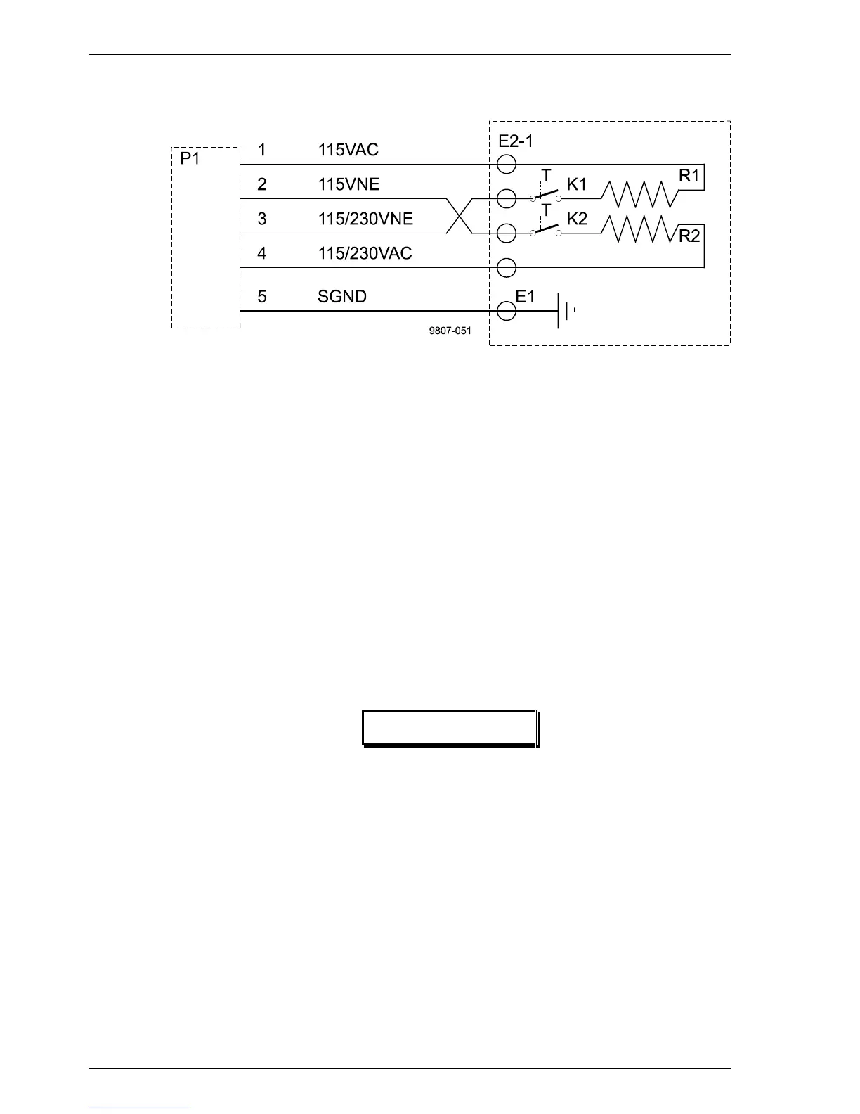
5.3.10 Internal Heaters Subassembly CT25039
Figure 5-15 CT25039 Wiring Diagram
The Internal Heaters subassembly CT25039 increases the temperature in the
area of the optical subassembly to prevent the lens and the measurement unit
window from becoming wet or misty. At the same time it also keeps the
whole interior above condensation temperature.
The heating subassembly consists of two power resistors with radiation
elements made of aluminium. This provides a good thermal contact with the
base plate and transmission of heat to the ambient air. Thermal switches
protect the system against overheating.
At 230 V supply voltage the resistors are connected in series by the line
voltage selection switch in the subassembly CTP241 and at 115 V supply
voltage they are connected in parallel. A relay in the CTP241 switches power
on/off under software control via DPS52.
WARNING
The heating resistors can be very hot even after the
heating has been switched off! Be cautious when working
in the vicinity of the heating!
Specifications:
Maximum power 180W (115VAC +15%, 230VAC +15%)
Max. surface temperature 130
°
C
Heating resistors (R1, R2):
- type HS100
- resistance 220Ω
- power 100W