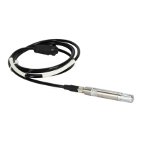
Ceilometer CT25K
User’s Guide CT25K-U059en-2.1
108
If this value remains in the range 300...400, it is acceptable.
7. Wait again for at least one measurement cycle (15 seconds), and give the
GET STATUS command. Check once more from the status message the
Receiver COMP values. These should be the same as before, indicating
that the automatic adjustment has stabilized.
8. Turn the power off and start the Ceilometer again in order to verify that
the unit is operating properly
8.5 Receiver CTR21
8.5.1 Removal
WARNING
Hazardous voltage 500 V is present at the Receiver and at
the Board Frame DMF51. Both the line and the battery
switches must be turned off before removing the Receiver.
When there is reason to suspect malfunction of the Receiver (i.e. Receiver
Failure Alarm or Receiver Optical Crosstalk Compensation Poor Warning
exist) follow the instructions below (First note Paragraph 8.3 Start-up
procedure.). In case there is reason to suspect failure in the Coaxial Cable
instead of the Receiver, refer to Paragraph 8.5.3. In case the compensation
fiber is suspected, refer to Paragraph 8.6.
1. Detach the Compensation Fiber from the receiver by loosening the screw
(See Figure 8-5) with a 1.5 mm hexagon key and pulling the fiber end
gently out. Do not twist the compensation fiber.
2. Detach the Receiver Ribbon Cable Connector from the connector J11 at
the DMF51 Board Frame by pressing the connector latches apart. Refer to
Figure 8-1.
3. Detach the Coaxial Cable from the DCT51 front panel.
4. Loosen the attachment ring (See Figure 8-5) using a 2.5 mm hexagon key
as a lever; there are holes in the attachment ring for that purpose. If the
Receiver begins to move along, stop it by hand. The photo diode has been
centered at the factory - do not apply force to the Receiver because that
may disturb the centering. Take the receiver into your hand and detach the
Coaxial Cable from it.
5. Send the defective receiver to Vaisala.
 Loading...


