Ceilometer CT25K
CT25K-U059en-2.1 User’s Guide
61
the flash AD converter. The gain control as well as the bandwidth selection
are automatic and controlled by the processor software and the DCT51.
WARNING
Dangerous voltages are present in this instrument. Use
extreme caution when handling, testing, and adjusting.
5.3.4 Optics Monitor CTL21
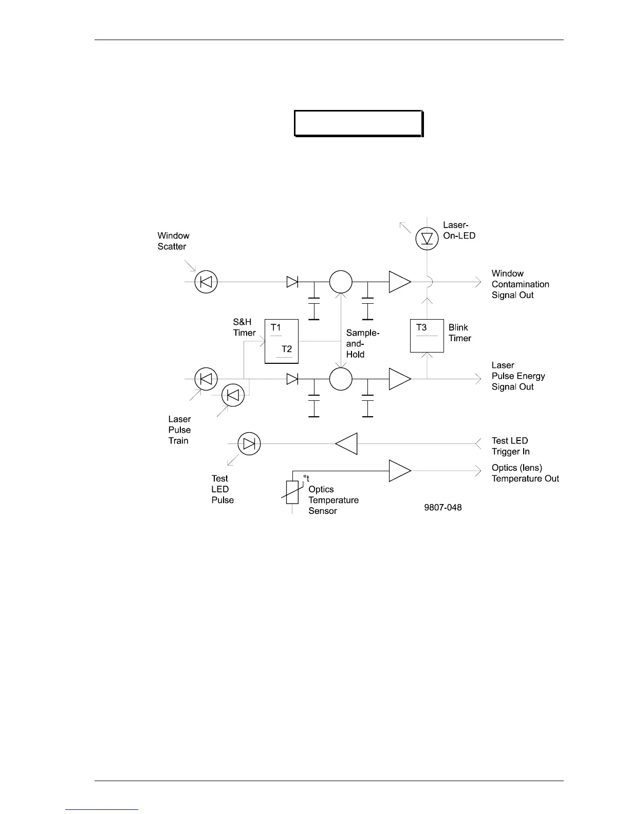
Figure 5-8 CTL21 Block Diagram
The laser pulse train sent from the laser transmitter CTT21 is monitored by
two PIN photodiodes. After a corresponding amplification and AD conversion
on the processor board, the signal is used as a control signal for the laser
output power. The pulses also give a start signal for a sample & hold circuit,
which, through a further photodiode, measures the light reflected back from
the window due to contamination. This signal is also transferred further to the
processor board A-to-D Converter and software, to give an indication of
window contamination. A Blink Timer controls an LED indicator which
indicates when the laser is switched on, i.e. sends laser pulses.
For testing of the complete receiver subsystem a short pulse is sent from a test
LED in the direction of the receiver. The control signal for triggering the test
LED is given from the ceilometer interface board DTC51. The optics is heated
in order to protect it against condensed humidity. A temperature sensor