Ceilometer CT25K
User’s Guide CT25K-U059en-2.1
iv
LIST OF FIGURES
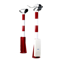
Figure 1-1 Ceilometer CT25K ..........................................................................................1
Figure 1-2 Data Line Connection Options.........................................................................5
Figure 2-1 Measurement Unit Handle.............................................................................10
Figure 2-2 Foundation Construction ...............................................................................11
Figure 2-3 Mounting the Pedestal...................................................................................12
Figure 2-4 Attaching the Measurement Unit and the Shield............................................13
Figure 2-5 External Connectors (bottom view) ...............................................................15
Figure 2-6 Termination Box Wire Connections ..............................................................16
Figure 3-1 CT25K Switches and LEDs...........................................................................20
Figure 4-1 Operation Modes ...........................................................................................25
Figure 4-2 Open and closed port.....................................................................................26
Figure 5-1 Typical Measurement Signal .........................................................................49
Figure 5-2 Measurement Unit Components.....................................................................53
Figure 5-3 Subassembly Interconnections.......................................................................54
Figure 5-4 Block Diagram of Operational Units .............................................................56
Figure 5-5 Optical Subassembly CTB22 with Optics Monitor, Transmitter and Receiver
Subassemblies...............................................................................................58
Figure 5-6 CTT21 Block Diagram ..................................................................................59
Figure 5-7 CTR21 Block Diagram..................................................................................60
Figure 5-8 CTL21 Block Diagram ..................................................................................61
Figure 5-9 DMF51 Frame ...............................................................................................62
Figure 5-10 DMC50B Block Diagram ............................................................................63
Figure 5-11 DIP Switch Settings of the DMC50 .............................................................66
Figure 5-12 DPS52 Block Diagram.................................................................................67
Figure 5-13 DCT51 Block Diagram................................................................................69
Figure 5-14 CTP241 Wiring ...........................................................................................71
 Loading...


