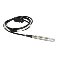
Ceilometer CT25K
CT25K-U059en-2.1 User’s Guide
81
TxD This LED will flash whenever the DMX611 sends data to the CT25K
(or to any device attached to the front panel TxD output).
Connector layout
Phone jack
The front panel has a six pin modular phone jack, that is labeled TEST. It is
designed for a hand held testset. The phone jack will allow communication to
the CT25K via the iSi. To verify proper operation of the DMX611, the phone
jack will also allow direct Inet communication to the Router, iSi and the front
panel isolated Inet connection.
20-pin connector on the front panel
1 CASE Case Ground
2 ⊥ 5V and 12V Common
3 IS-HI Isolated RS485 High (Inet)
4 IS-LO Isolated RS485 Low (Inet)
5 IS ⊥ Isolated RS485 Common
6 TxD RS232 Input
7 PTT 2 Channel 2 Radio Link PTT
8 RxSH2 Radio Link/Wire Link Channel 2 High
9 RxSL2 Radio Link/Wire Link Channel 2 Low
10 CASE Case Ground
11 RxD RS232 TTL Level Output
12 PTT 1 Channel 1 Radio Link PTT
13 RxSH1 Radio Link/Wire Link Channel 1 High
14 RxSL1 Radio Link/Wire Link Channel 1 Low
15 CASE Case Ground
16 AN2HI Anet Channel 2 High
17 AN2LO Anet Channel 2 Low
18 AN1HI Anet Channel 1 High
19 AN1LO Anet Channel 1 Low
 Loading...


