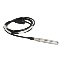
Ceilometer CT25K
User’s Guide CT25K-U059en-2.1
82
20 CASE Case Ground
DIP Switch Settings
S1
(Router Node ID)
S2
(iSi Device ID)
S1:1 LSB - Node ID S2:1 LSB – Device ID
S1:2 | S2:2 |
S1:3 | S2:3 |
S1:4 | S2:4 MSB - Device ID
S1:5 |
S1:6 |
S1:7 |
S1:8 MSB - Node ID
S3 S4
S3:1 (keep closed) S4:1 (keep on)
S3:2 RFDATA - iBi2 S4:2 RFDATA - iBi1
S3:3 Wire HI - iBi2 S4:3 Wire LO - iBi1
S3:4 Wire LO - iBi2 S4:4 Wire HI - iBi1
S4:5 (keep on)
Descriptions:
LSB Least Significant Bit
MSB Most Significant Bit
For switch S1: OPEN = Logic 0
For switch S2: OPEN = Logic 1
Switch 3 and 4 settings:
S3:2 – OPEN for wire link – CLOSED for radio link
S3:3 – CLOSED for wire link – OPEN for radio link
S3:4 – CLOSED for wire link – OPEN for radio link
S4:2 – OFF for wire link – ON for radio link
S4:3 – ON for wire link – OFF for radio link
S4:4 – ON for wire link – OFF for radio link
 Loading...


