Ceilometer CT25K
User’s Guide CT25K-U059en-2.1
110
Check that the receiver is now in the correct position, that is, the long
edges of the receiver case are approx. horizontal. If this is not the case,
loosen the attachment ring first, then correct the receiver position and
fasten as described above.
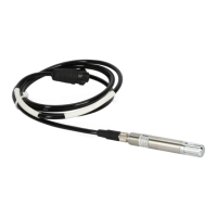
3. Plug the Compensation Fiber into the receiver and tighten the screw
(marked Fibre attachment) with a 1.5 mm hexagon key.
4. Attach the Coaxial Cable to the J1 connector at the front panel of DCT51.
5. Attach the ribbon cable connector to DMF51 Board Frame connector J11.
Refer to Figure 8-1.
6. Connect the Power Cable and the Maintenance Terminal. Turn the power
on.
7. If the receiver has been replaced by a new one, do the following
parameter settings:
a) Open the command set by first typing OPEN↵ at the command prompt
and then typing the password ADVANCED↵.
b) Adjust the internal crosstalk compensation according to Paragraph
8.4.3.
c) Turn the power off and start the Ceilometer again in order to run the
automatic receiver self-check.
d) Open the command set by first typing OPEN↵ at the command prompt
and then typing the password ADVANCED↵.
e) Interrupt autoadjustments with the command
STOP↵
Then give the following commands:
SET PORT TIMEOUT 20↵ sets the timeout of the dialog
to 20 minutes
SET DATA_ACQ INTERVAL 15↵ sets minimum measurement
interval
f) Give the command
GET STATUS↵
Wait until the SENS parameter under the title Receiver in the status
message gets a value. It may take a couple of minutes, because the
automatic receiver self-check is performed during the fourth
measurement cycle.
 Loading...


