2.5.3 Transmitter Board
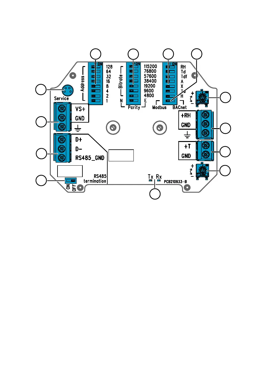
Figure 4 HMD65 Transmitter Board: Service Port, DIP switches, Trimmers, and Screw Terminals
1
RS-485 termination (120 Ω resistor) ON/OFF switch.
2 RS-485 (Modbus/BACnet) screw terminals.
3 Power supply input (15 … 35 VDC or 16 … 24 VAC) screw terminals.
4 Service port for MI70 hand-held indicator and Insight PC software cable connection.
5 DIP switches for setting the HMD65 Modbus RTU or BACnet MS/TP MAC address.
6 DIP switches for selecting Modbus/BACnet communication bit rate and parity (Modbus
only).
7 DIP switches for humidity output parameter selection.
8 DIP switch for selecting either Modbus or BACnet mode.
9 Trimmer for humidity measurement adjustment.
10 Screw terminals for humidity measurement output.
11 Screw terminals for temperature measurement output.
12 Trimmer for temperature measurement adjustment.
13 Indicator LEDs: flash when there is RS-485 transmit (TX) or receive (RX) activity.
More Information
‣
Wiring (page 16)
‣
Modbus and BACnet Overview (page 26)
Chapter 2 – Product Overview
9

 Loading...


