3.2 Duct Mounting Overview
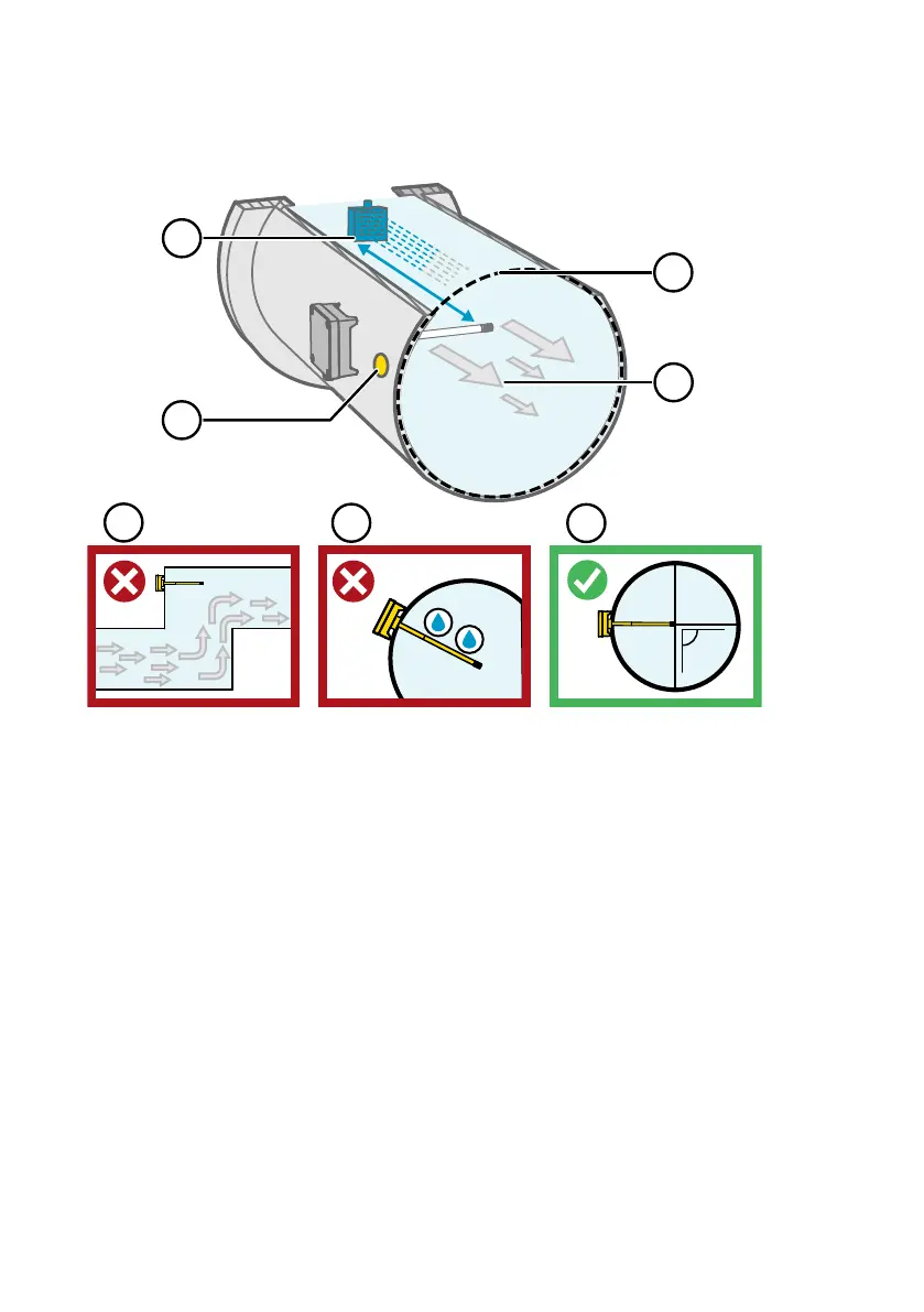
Figure 9 Duct Installation Overview
1
Make sure there is a minimum clearance of 5 m (16.5 ft) between the probe body and any
possible humidifier. Avoid installing in a location where condensation can fall on the
sensor inside the duct.
2 When installing the transmitter, drill a second hole approximately 30 cm (12 in) from the
installation hole, towards the direction of the air flow, and plug it with a removable seal.
This second hole is intended for later use in reference measurement with another device
when calibrating or adjusting the transmitter.
3 Check that the duct diameter is suitable for the probe body (see Transmitter Dimensions
(page 13)). Ideally, the sensor (probe head) should be installed in the middle of the duct.
4 Maximum air flow speed: 50 m/s (with sintered filter).
5 Avoid installing the transmitter in dead legs. Supersaturation can occur in areas where
there is no air flow.
6 Do not install the probe in a downward angle. Condensation can travel to the sensor along
the probe body if the probe points down.
7 Install the probe in a 90° angle so that the sensor is placed as close to the middle of the
duct as possible.
HMD65 User Guide M212243EN-A
14

 Loading...


