3.3 Installing into Duct
• Medium size crosshead screwdriver for mounting screws and lid screws.
• Small slotted screwdriver for screw terminals.
• Drill with 3.5 mm (0.14 in) and 13 … 15 mm (0.51 … 0.59 in) bits for making the
installation holes.
• Tools for cutting and stripping wires.
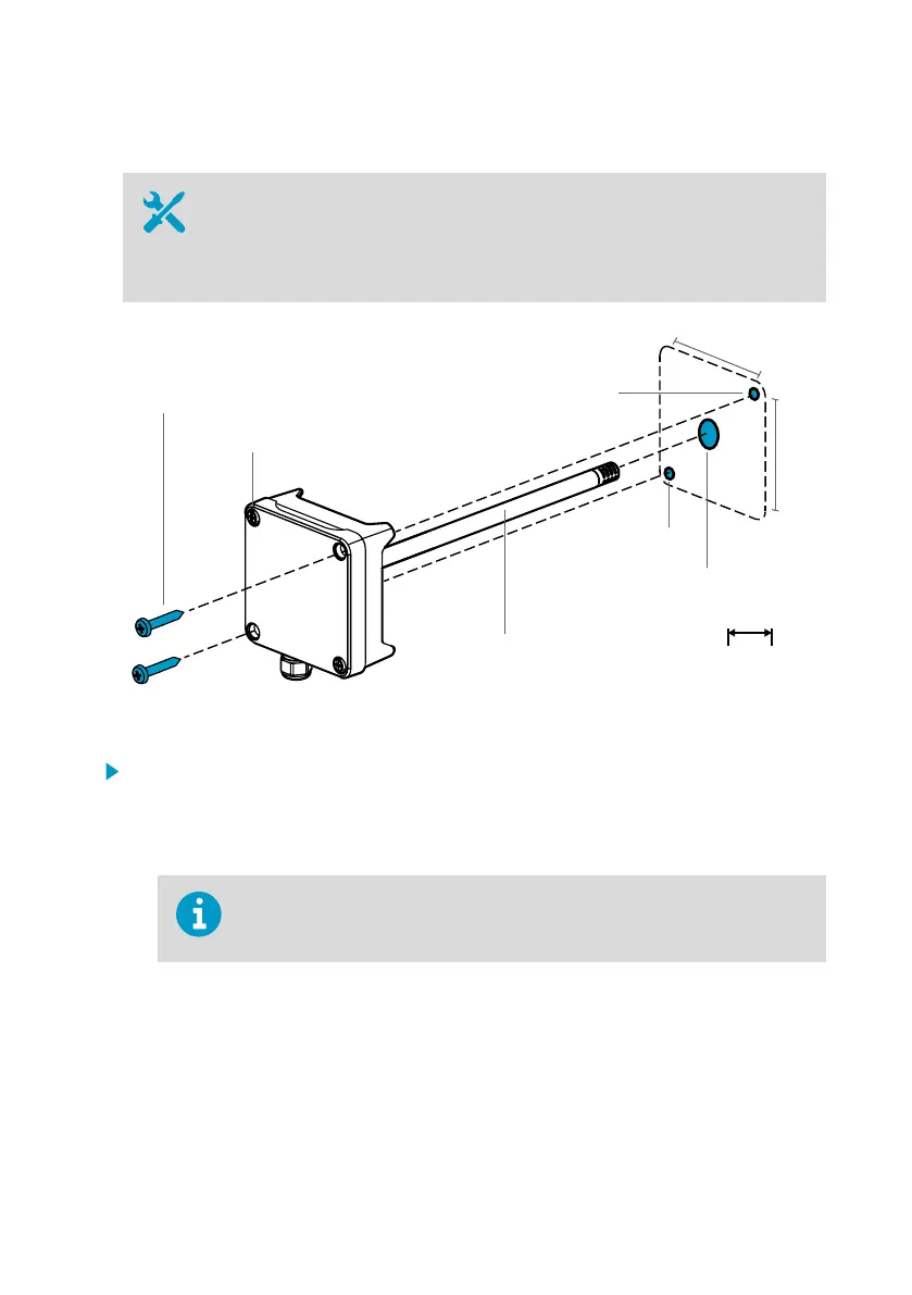
2 x Ø 3.5 [0.14]
Ø 13 ... 15 [0.51 ... 0.59]
Ø 12 [0.47]
mm
[in]
Ø 3.5 [0.14]
Ø 3.5 [0.14]
3.1 ... 3.4 Nm [2.3 ... 2.5 ft-lbs]
Figure 10 Drilling and Mounting Screws
1. Select an installation location for the transmitter on the duct surface and drill a
Ø 13 … 15 mm (0.51 … 0.59 in) hole for inserting the probe.
2. Push the probe through the hole on the duct until the transmitter body meets the duct.
3. Attach the transmitter body to the duct with 2 Ø 3.5 mm (0.14 in) screws.
Check that the insulation ring sits tightly over the installation hole. If the duct
has a negative pressure, external air can be drawn into the duct and aect
the measurement if the installation hole is not sealed tightly.
4. Optional: Drill a second hole for reference measurements approximately 30 cm (12 in)
from the transmitter installation hole. See Figure 9 (page 14).
5. Open the 2 captive screws on the transmitter body and remove the lid.
6. Attach the input/output wiring to the screw terminals on the transmitter component
board. See Wiring (page 16). Tighten cable glands firmly after wiring.
7. Check that the DIP switches and trimmers are in the correct position. See Transmitter
Board (page 9) for more information on DIP switches and trimmers.
Chapter 3 – Installation
15

 Loading...


