Appendix B. BACnet Reference
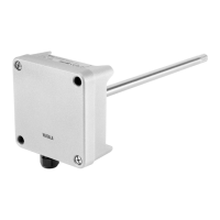
This appendix describes the BACnet protocol implementation of the HMD65 relative humidity
and temperature transmitter.
Implementation
The BACnet standard has many options for both physical and data link layers. HMD65
implements the following communication options:
• MS/TP Master
MS/TP Master
Master mode operation means that the HMD65 transmitter is part of a token passing loop.
Master can send messages to the MS/TP bus when it has received a token. According to
BACnet standard, the master address must be in the range 0 … 127. For correct operation,
Master mode also requires that the parameter MAX_MASTER is set. It must be same in every
master node connected to the same bus segment. MAX_MASTER defines highest MAC address
used by master nodes. For instructions on configuring the MAX_MASTER parameter with
Vaisala Insight PC software, see Configuring BACnet with Insight (page 28).
Master functionality enables automatic network setup. The client can send inquiries such as
“who has property XYZ” or “who is device number 12345”. The device replies to inquiries when
it is available to talk. When the master mode device has no token it behaves as a slave, that is,
it replies to requests.
MAC Address
The MS/TP address for MS/TP master is 0 … 127. The address is selected by DIP switches: see
Modbus and BACnet Overview (page 26).
Communication Parameters
The fixed serial line parameters are: No parity, 8 Databits and 1 Stop bit.
The communication speed is selected by DIP switches. The supported communication speeds
are 9600, 19200, 38400, 57600, 76800 and 115200.
If DIP switches are set to select 4800 bps, 38400 is used instead. 4800 bps is not a supported
BACnet baud rate.
Physical Interface
The physical interface for using HMD65 through BACnet is galvanic isolated RS-485. There are
weak pull-up and pull-down resistors (100k) from data lines to +3.3VDC and GND. A
termination resistor (120 ohm) can be connected between data lines with a DIP switch on the
HMD65 component board. Three screw terminals are needed: D+ (485+), D- (485-) and GND
(RS485_GND). For DIP switch and screw terminal locations, see Figure 18 (page 26).
HMD65 User Guide M212243EN-A
54

 Loading...