User’s Guide ______________________________________________________________________
58 __________________________________________________________________ M211840EN-C
Wiring with 8-pin M12 Connector
External Wiring
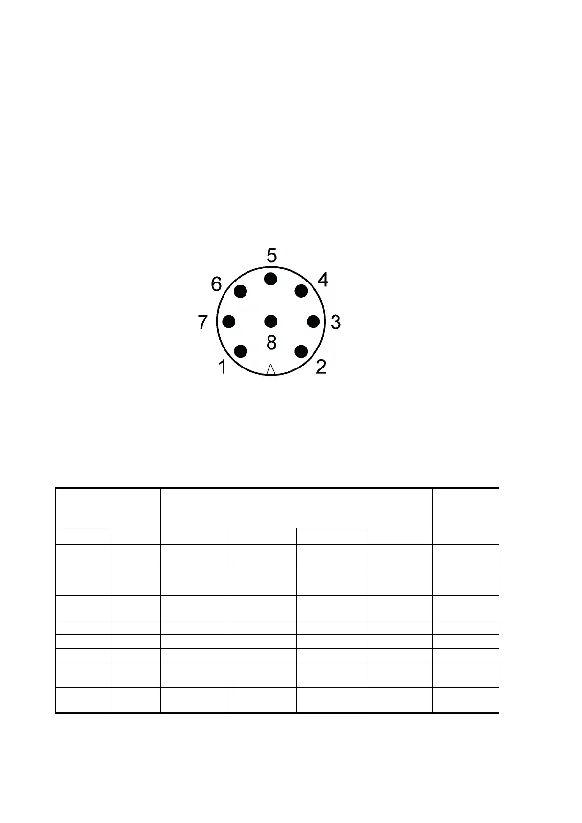
The 8-pin M12 connector is located on the bottom of the transmitter.
The following figure shows the pins of the 8-pin M12 connector as seen
from outside the transmitter.
1509-091
Figure 31 Pins of 8-pin M12 Connector
The table below shows the pin connections for the 8-pin M12 connector
and the wire colors of the respective M12 cable (optional, 2/10 m).
Table 4 Pin-outs for WXT530 Series Serial Interfaces and
Power Supplies
Available for all WXT530 Series models WXT532
additional
option
Wire Color M12 Pin# RS-232 SDI-12 RS-485 RS-422 mA Output
White 1 Data in
(RxD)
Data in/out
(Rx)
- Data out
(TX-)
Iout2
Brown 2 Vin+
(operating)
Vin+
(operating)
Vin+
(operating)
Vin+
(operating)
Vin+
(operating)
Green 3 GND for data GND for data GND for data Data out
(TX+)
GND Iout2
Yellow 4 Vh+ (heating) Vh+ (heating) Vh+ (heating) Vh+ (heating) Vh+ (heating)
Gray 5 - - Data+ Data in (RX+) GND Iout1
Pink 6 Vh- (heating) Vh- (heating) Vh- (heating) Vh- (heating) Vh- (heating)
Blue 7 Data out
(TxD)
Data in/out
(Tx)
Data- Data in (RX-) Iout1
Red 8 Vin-
(operating)
Vin-
(operating)
Vin-
(operating)
Vin-
(operating)
Vin-
(operating)