7.4 Current Transformer Selection
VAMP 24h support phone +358 (0)20 753 3264
7.4. Current Transformer Selection
Iron core current transformers (CT) are accurate in amplitude
and phase when used near their nominal values. At very low
and at very high currents they are far from ideal. For over-
current and differential protection, the actual performance of
CTs at high currents must be checked to ensure correct
function of the protection relay.
7.4.1. CT classification according IEC 60044-1, 1996
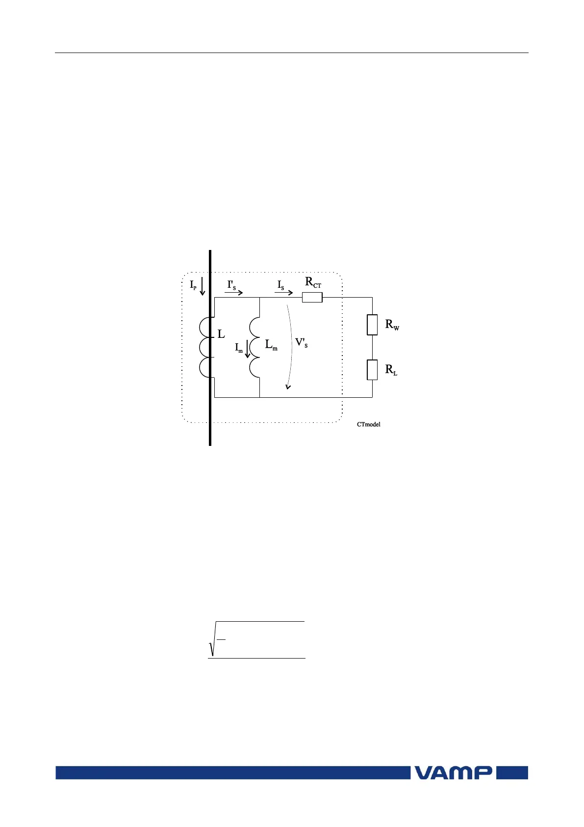
CT model
Figure 7.4.1-1 A CT equivalent circuit. L
m
is the saturable magnetisation
inductance, L is secondary of an ideal current transformer, R
CT
is resistance
of the CT secondary winding, R
W
is resistance of wiring and R
L
is the burden
i.e. the protection relay.
Composite error
C
Composite error is the difference between the ideal secondary
current and the actual secondary current under steady-state
conditions. It includes amplitude and phase errors and also the
effects of any possible harmonics in the exciting current.
Equation 7.4.1-1
%100
)(
1
2
0
P
T
PSN
C
I
dtiiK
T
Rated transformation ratio I
NPrimary
/I
Nsecondary
Instantaneous secondary current
Instantaneous primary current
Rms value of primary current