VAMP 24h support phone +358 (0)20 753 3264
9. Technical data
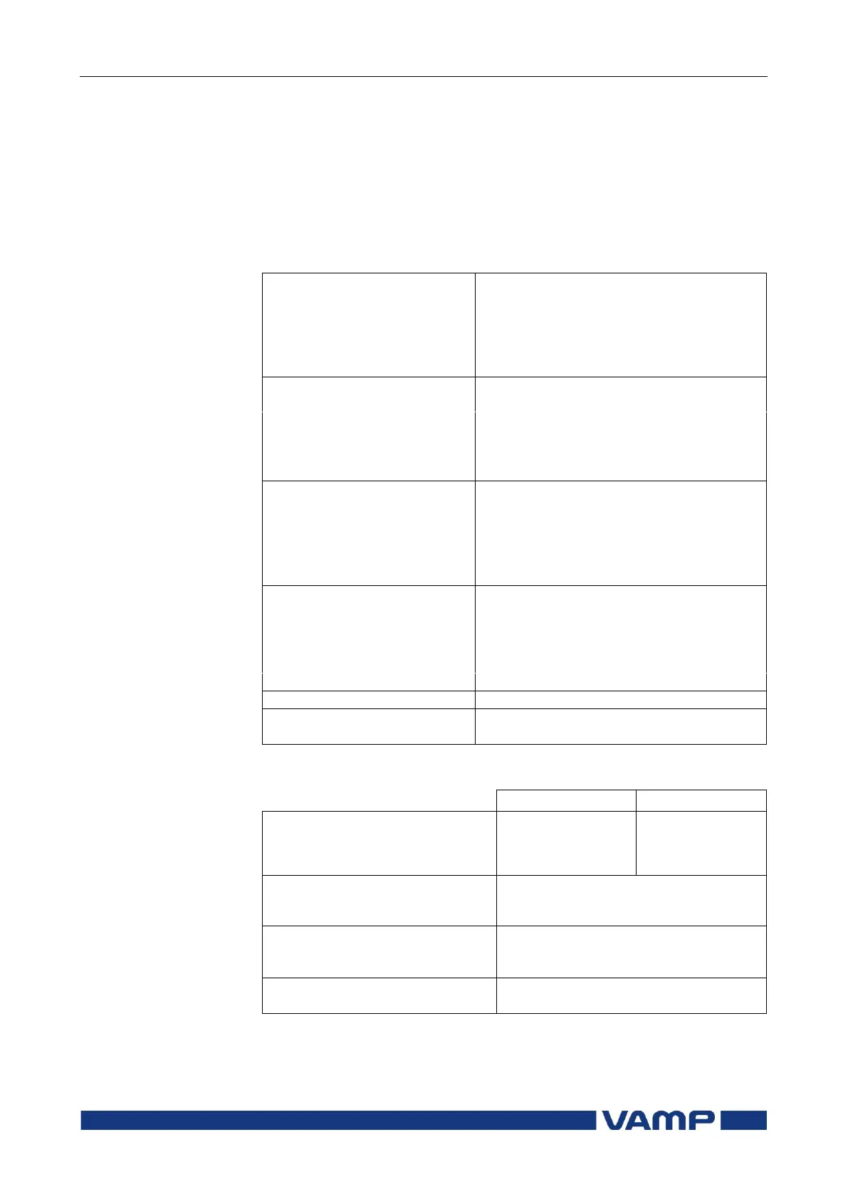
9.1. Connections
9.1.1. Measuring circuitry
5 A (configurable for CT secondaries 1 – 10 A)
- Current measuring range
1 A (configurable for CT secondaries 1 – 10 A)
- Current measuring range
Rated residual current (optional)
5 A (configurable for CT secondaries 1 – 10 A)
- Current measuring range
1 A (configurable for CT secondaries 0.1 – 10 A)
- Current measuring range
9.1.2. Auxiliary voltage
18...36 Vdc
Note! Polarity.
X3:17= negative (-)
X3:18= positive (+)
Start-up peak (DC)
110V
220V
15A with time constant of 1ms
25A with time constant of 1ms
< 7 W (normal conditions)
< 15 W (output relays activated)
Max. permitted interruption time
- Phoenix MVSTBW or equivalent