Operation and configuration
instructions
2 Local panel user interface
2.4 Configuration and parameter
setting
VAMP 24h support phone +358 (0)20 753 3264
For details see the technical description part of the manual.
DNP3
Only one instance of this protocol is possible.
Bit rate [bit/s]. Default is "9600".
[Parity].
Addres for this device [SlvAddr]. This address has to be
unique within the system.
Master's addres [MstrAddr].
For further details see the technical description part of the
manual.
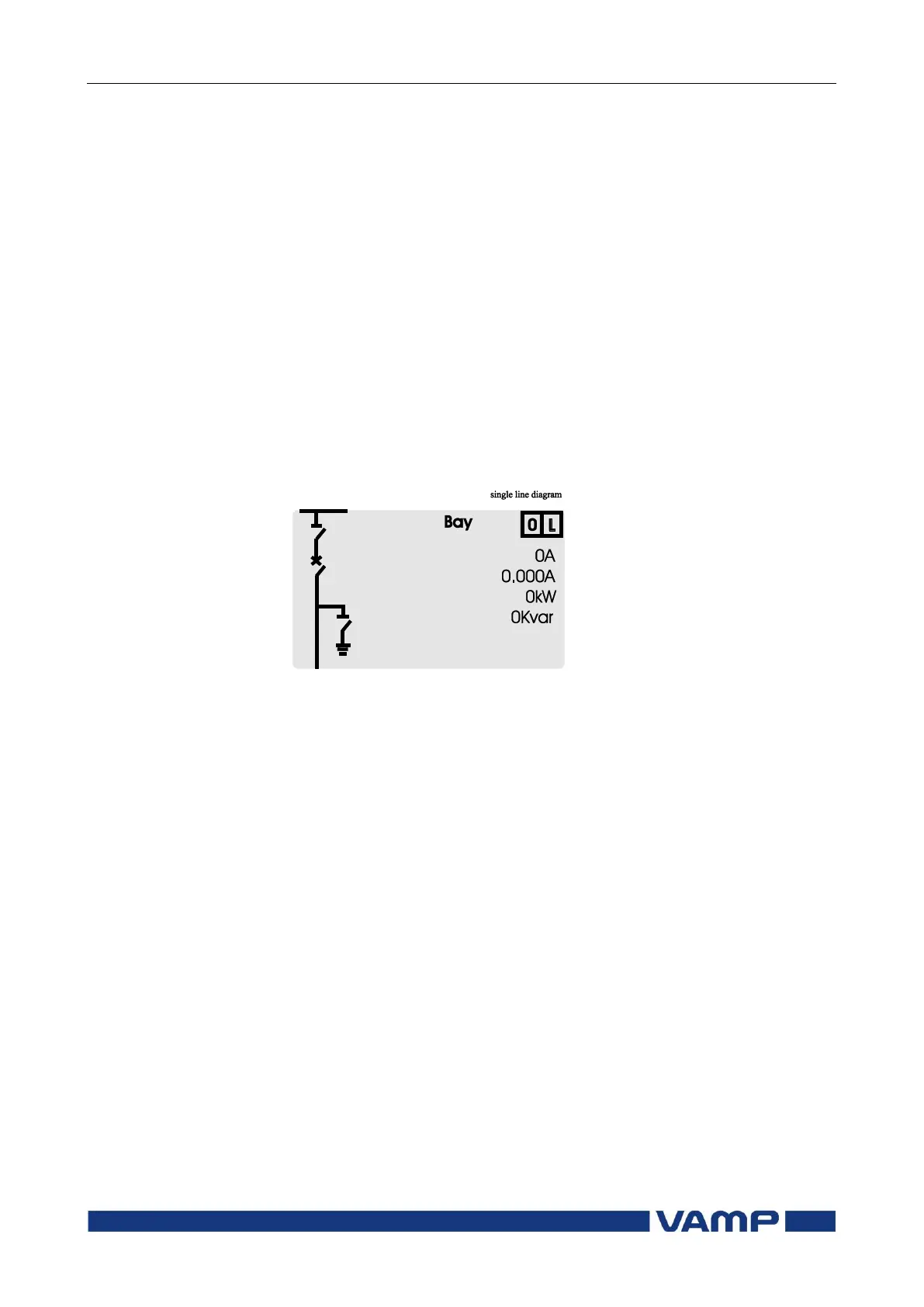
2.4.9. Single line diagram editing
The single-line diagram is drawn with the VAMPSET software.
For more information, please refer to the VAMPSET manual
(VMV.EN0xx).
Figure 2.4.9-1. Single line diagram.
2.4.10. Blocking and interlocking configuration
The configuration of the blockings and interlockings is done
with the VAMPSET software. Any start or trip signal can be
used for blocking the operation of any protection stage.
Furthermore, the interlocking between objects can be
configured in the same blocking matrix of the VAMPSET
software. For more information, please refer to the VAMPSET
manual (VMV.EN0xx).