2 Local panel user interface
Operation and configuration
instructions
VAMP 24h support phone +358 (0)20 753 3264
2. Local panel user interface
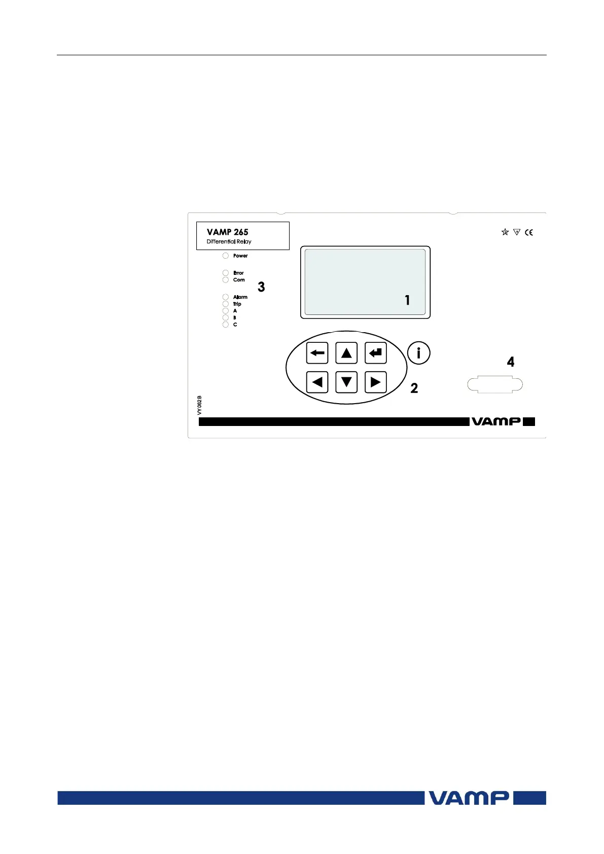
2.1. Relay front panel
The figure below shows, as an example, the front panel of the
relay VAMP 265 and the location of the user interface elements
used for local control.
Figure 2.1-1. The front panel of VAMP 265
1. LCD dot matrix display
2. Keypad
3. LED indicators
4. RS 232 serial communication port for PC