7.4 Current Transformer Selection
VAMP 24h support phone +358 (0)20 753 3264
7.4.2. CT Requirement for Protection
When the through current equals and exceeds k
A
xI
n
there may
be enough secondary differential current to trip a relay
although there is no in zone fault. This is because the CTs are
unique and they do not behave equally when approaching
saturation.
To avoid false trips caused by heavy through faults the actual
accuracy limit factor k
A
of the CTs should exceed the relative
setting I
SET
of the non-stabilized differential stage.
Equation 7.4.2-1
Relative setting of the non-stabilized differential current stage
Rated current of the transformer (primary side or secondary
side)
Rated primary current of the CT (primary side or secondary
side)
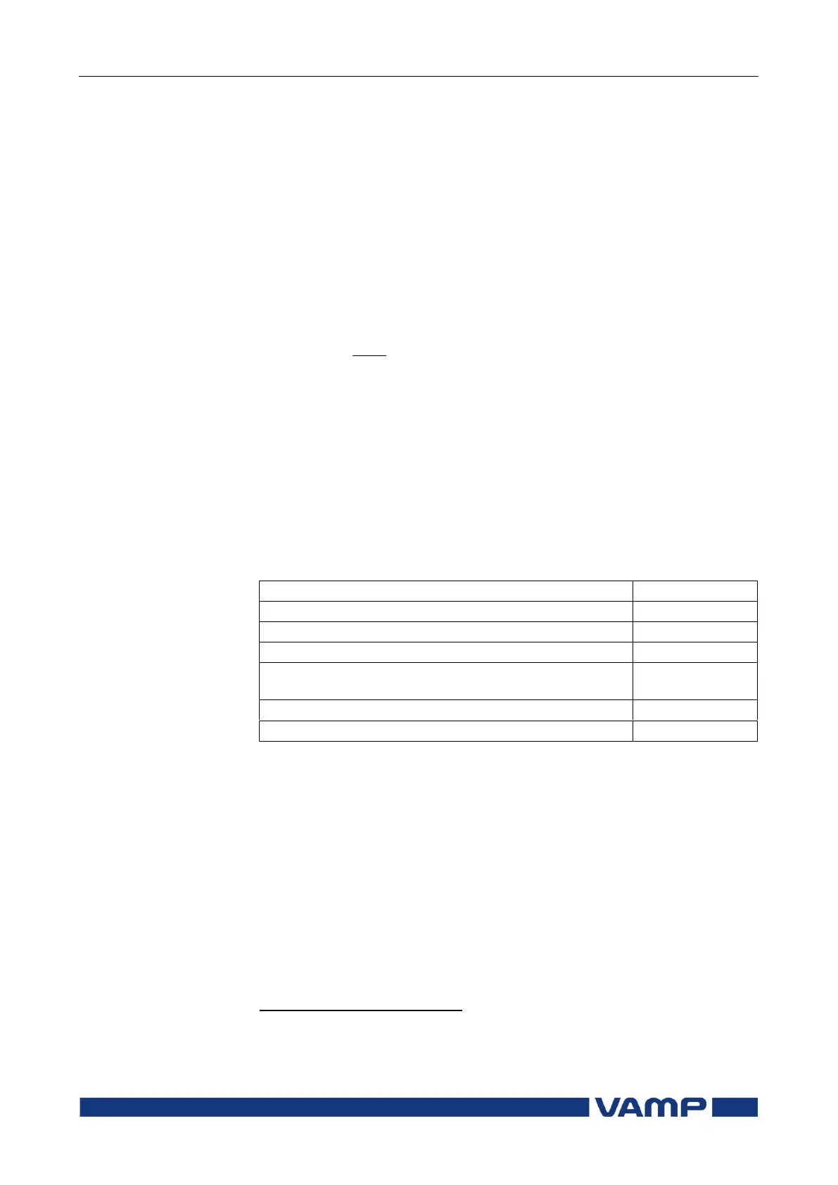
Using slightly smaller safety factor than indicated in the table
will increase the setting inaccuracy.
Earth-fault, cable transformer
Earth-fault overcurrent, sum of three phase currents
2
Transformer differential, -winding or unearthed Y-
winding
Transformer differential, earthed Y-winding
Sensitive earth-fault current settings, < 5% x I
N
, should be avoided in this
configuration because a set of three CTs are not exactly similar and will
produce some secondary residual current even though there is no residual
current in the primary side.