2.4 Differential overcurrent
protection ΔI> (87)
VAMP 24h support phone +358 (0)20 753 3264
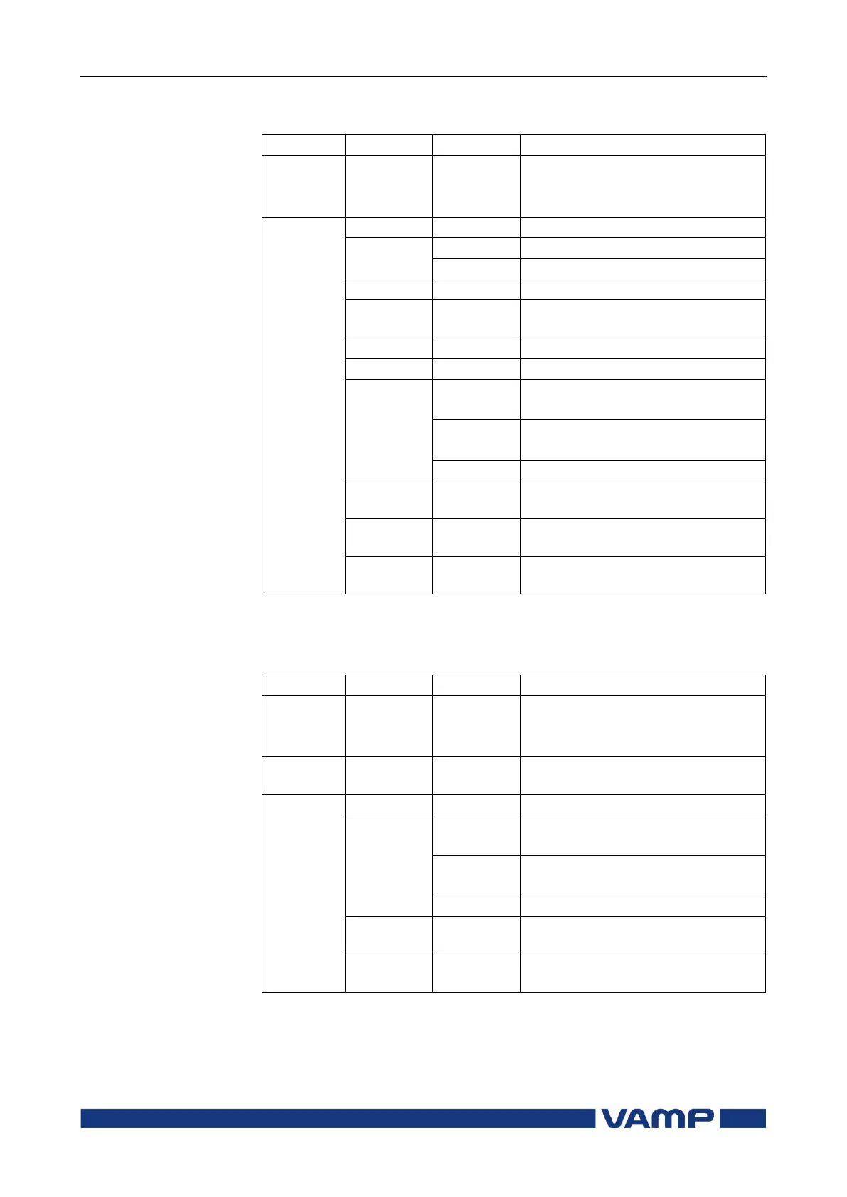
Parameters of the differential overcurrent stages I> (87):
Bias current start of slope 2
2. harmonic blocking
enable/disable
Fault type/single-phase fault e.g.:
1-N = fault on phase L1
Fault type/two-phase fault e.g.: 2-3
= fault between L2 and L3
Fault type/three-phase fault
Max. value of fault differential
current as compared to I
n
Value of bias current of faulted
phase as compared to I
n
1 s mean value of pre-fault phase
currents IL1…IL3
1) Measurement ranges are described in section 9.1.1.
2) Setting ranges are described in section 9.3.2.
Parameters of the differential overcurrent stages I>> (87):
Fault type/single-phase fault e.g.:
1-N = fault on phase L1
Fault type/two-phase fault e.g.: 2-3
= fault between L2 and L3
Fault type/three-phase fault
Max. value of fault differential
current as compared to I
n
1 s mean value of pre-fault phase
currents IL1…IL3