2.13 Inverse time operation
VAMP 24h support phone +358 (0)20 753 3264
Example of limitation
CT = 750/5
I
N
= 577 A
CT
0
= 100/1 (a cable CT for I
0
)
Secondary scaled I
GNsec
is now 3.85 A
For 5 A CT secondaries and 1 A residual current inputs VAMP
relay VAMP 265-5D7AAA is used. It has 5 A phase current
inputs and 1 A residual inputs.
For overcurrent stage I> the table below gives 12.5 A. Thus the
maximum setting for I> stage giving full inverse delay range is
12.5 A / 3.85 A = 3.25 xI
gn
.
For earth fault stage I
0
> and input I
01
the table below gives
0.25 A. Thus the maximum setting for I
0
> stage giving full
inverse delay range is 0.25 A / 1 A = 0.25 pu. This equals a 25 A
primary earth fault current.
When using input signal I
0Calc
the corresponding setting is 12.5
A / 1 A = 12.5 pu. This equals a 9375 A of primary earth fault
current.
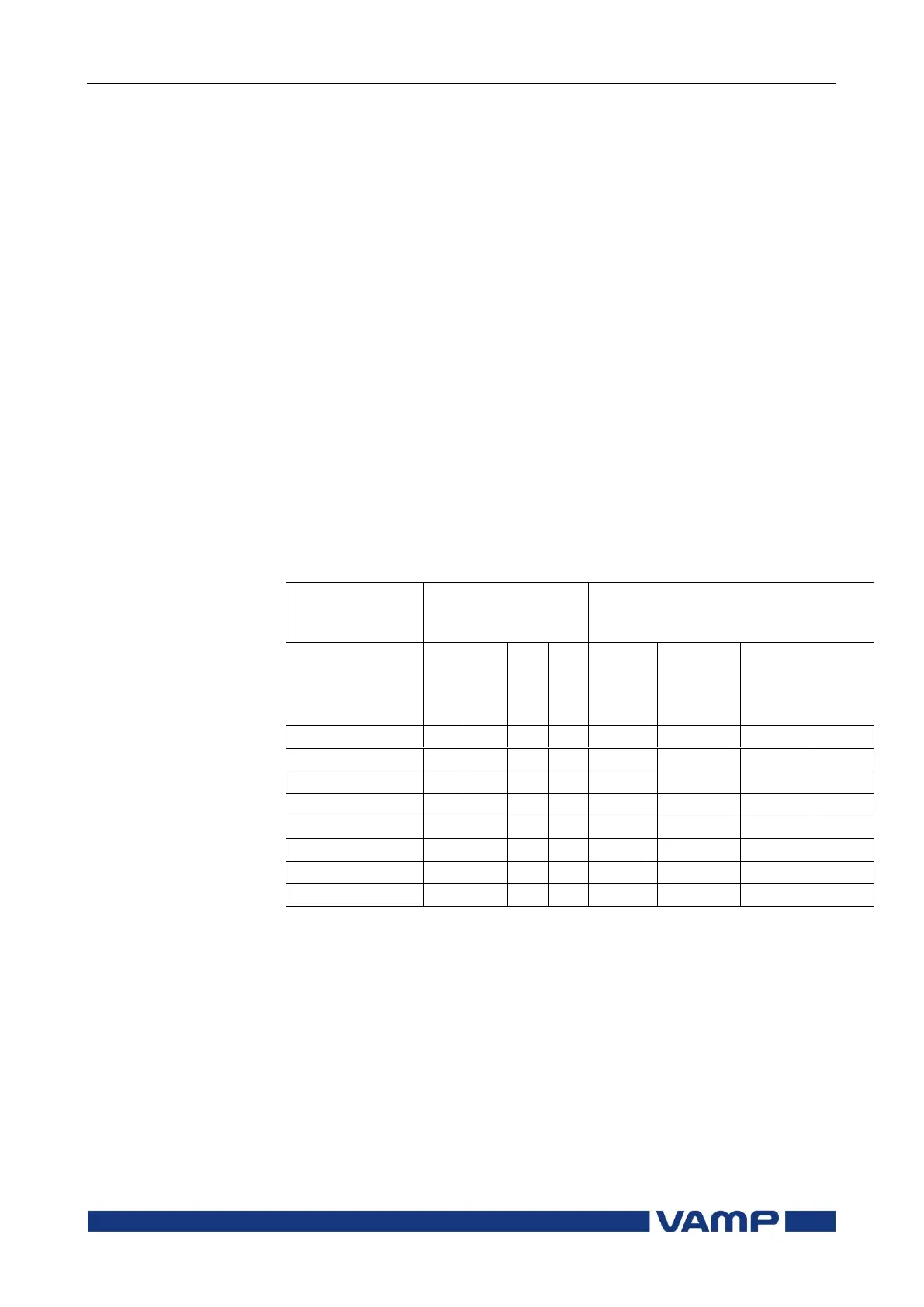
Maximum secondary scaled setting
enabling inverse delay times up to
20x setting
I’
L1
, I’
L2
,
I’
L3
&
I’
0Calc