Subject to modification! Updated 10/2017
Expansion stage element 3/6
Place the battery module in the storage cabinet according to
Figure 21: Installation positions of the battery modules.
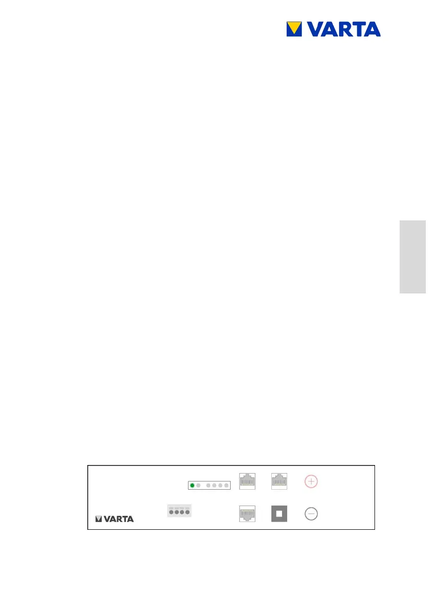
Connections at the battery module according to Figure 22:
Connections – expansion stage element 3/6:
Battery power connection:
Plug on both connectors with correct polarity.
Communication 1:
Insert the four communication cables into the openings in
the clamping connector.
The connections are self-clamping.
For the pin assignment, see Figure 20: Clamped
connections of battery module (DRY contact)
Communication 2:
Plug in communication cable 2 (red, CAN).
Fixation:
Slide the battery module towards the rear.
Fix at the fastening holes of the mounting rails by using
the supplied screws.
Aid: Allen key, size 4
Switching on the battery module:
Press the activation button on the battery module.
The LED indicator at the battery module indicates the
standby mode.