19
OPTIONAL
19
OPTIONALS
19
SONDERZUBEHOR
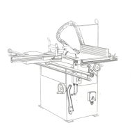
19.1
Carrello
a
bandiera
Tale attrezzatura consente
il
potenziamento
del
piano
di
lavoro,
rendendo
semplici
le
operazioni
su
pezzi
d
notevoli
dimension!.
19.2
Montaggio
del
carrello
a
bandiera
II
montaggio
del
carrello
a
bandiera
si
effettua
nel
seguente
modo:
*
montane
la
guida
(A)
sui
support)
lateral!
(B)
Fig.
19
gia
fissati
alia
macchina
*
togliere
dalla
parte
del
piano
di
entrata
la
rondella
di
battuta
con la sua
vite
(C)
Fig.
19
*
disporre
il
sostegno
snodato
(D)
come
in
Fig.
19
*
inserire
il
carrello
(E)
nella
guida
(A)
mediante
i
rotismi
(F)
Fig.
19
*
inserire
Pasta
(G) del
sostegno snodato
nell'apposito
foro
sotto
il
carrello
(E)
Fig.
19
*
allineare
il
carrello
col
piano sega,
allentando
il
dado
(H)
Fig.
19 ed
awitando
o
svitando
I'asta
(G)
*
montare
la
rondella
di
battuta
con la sua
vite
(C) fig.19
II
carrello
e
fomito
delta
guida
telescopica
a
squadrare
(I)
Fig.19A
che
puo
estendersi
allentando
la
leva
(L)
Fig.19A
fissata
suli'estensione
della
guida.
La
guida
puo
ruotare
allentando
la
leva
(M)
Fig.19A
e
I'inclinazione
si puo
leggere
sulla
targhetta
(N)
Fig.19A
posta
sul
carrello
(E)
Fig.19A.
Per
il
serraggio
del
pezzo,
agire
sullo
stringipezzo
(0)
Fig.19A.
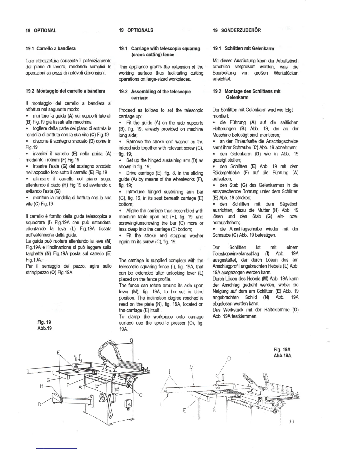
Fig.
19
Abb.19
19.1 Carriage with telescopic squaring
(croos-cutting)
fence
This
appliance
grants
the
extension
of the
working
surface thus
facilitating
cutting
operations
on
large-sized
workpieces.
19.2 Assembling
of the
telescopic
carriage
Proceed
as
follows
to set the
telescopic
carriage
up:
* Fit the
guide
(A) on the
side supports
(B),
fig. 19,
already provided
on
machine
long side;
*
Remove
the
stroke
end
washer
on the
infeed
side together with relevant
screw
(C),
fig.
19;
* Set up the
hinged sustaining
arm (D) as
shown
in
fig.
19;
*
Drive carriage
(E), fig.
8, in the
sliding
guide
(A) by
means
of the
wheelworks
(F),
fig-19;
*
Introduce hinged sustaining
arm bar
(G),
fig.
19, in its
seat beneath carriage
(E)
bottom;
*
Aligne
the
carriage thus assembled with
machine table upon
nut
(H), fig.
19, and
screwing/unscrewing
the bar (G)
more
or
less deep into
the
carriage
(E)
bottom;
* Fit the
stroke
end
stopping washer
again
on its
screw (C),
fig.
19.
The
carriage
is
supplied
complete with
the
telescopic
squaring fence
(I), fig.
19A, that
can
be
extended after unlocking lever
(L)
placed
on the
fence profile.
The
fence
can
rotate around
its
axle upon
lever
(M), fig. 19A,
to be set in
tilted
position.
The
inclination degree reached
is
read
on the
plate
(N), fig. 19A,
located
on
the
carriage
(E)
itself.
To
clamp
the
workpiece
onto carriage
surface
use the
specific
presser
(0), fig.
19A.
19.1
SchlittenmitGelenkarm
Mit
dieser
Ausrustung
kann
der
Arbeitstisch
erheblich
vergroSert
werden,
was die
Bearbeitung
von
gro&en
Werkstucken
erleichtet.
19.2 Montage
des
Schlittens
mil
Gelenkarm
Der
Schlitten
mit
Gelenkarm
wird
wie
folgt
montiert
* die
Fiihrung
(A)
auf
die
seitlichen
Halterungen
(B)
Abb.
19, die an der
Maschine
befestigt
sind,
montieren;
* an der
Einlaufseite
die
Anschlagscheibe
samt
ihrer
Schraube
(C)
Abb.
19
abnehmen;
* den
Gelenkarm
(D) wie in
Abb.
19
gezeigt
stellen;
* den
Schlitten
(E)
Abb.
19 mit
dem
Radergetriebe
(F) auf die
Fuhrung
(A)
aufsetzen;
* den
Stab
(G) des
Gelenkarmes
in die
entsprechende
Bohrung
unter
dem
Schlitten
(E)
Abb.
19
sleeken;
* den
Schlitten
mit dem
Sagetisch
ausrichten,
dazu
die
Mutter
(H)
Abb.
19
losen
und
den
Stab
(G)
ein- bzw.
herausdrehen;
* die
Anschlagscheibe
wieder
mit der
Schraube
(C)
Abb.
19befestigen.
Der
Schlitten
ist mit
einem
Teleskopwinkelanschlag
(I)
Abb.
19A
ausgestattet,
der
durch
Losen
des am
Anschlagprofil
angebrachten
Hebels
(L)
Abb.
19A
ausgezogen
werden
kann.
Durch
Losen
des
Hebels
(M)
Abb.
19A
kann
der
Anschlag
gedreht werden,
wobei
die
Neigung
auf dem am
Schlitten
(E)
Abb.
19
angebrachten Schild
(N)
Abb.
19A
abgelesen
werden kann.
Das
Werkstiick
mit der
Halteklemme
(0)
Abb.
19Afestklemmen.
Fig.
19A
Abb.19A
33