Item Description
1 Operation/Display panel
2 Upper bezel
3 Lower bezel/battery access door
2.3 Rear Panels
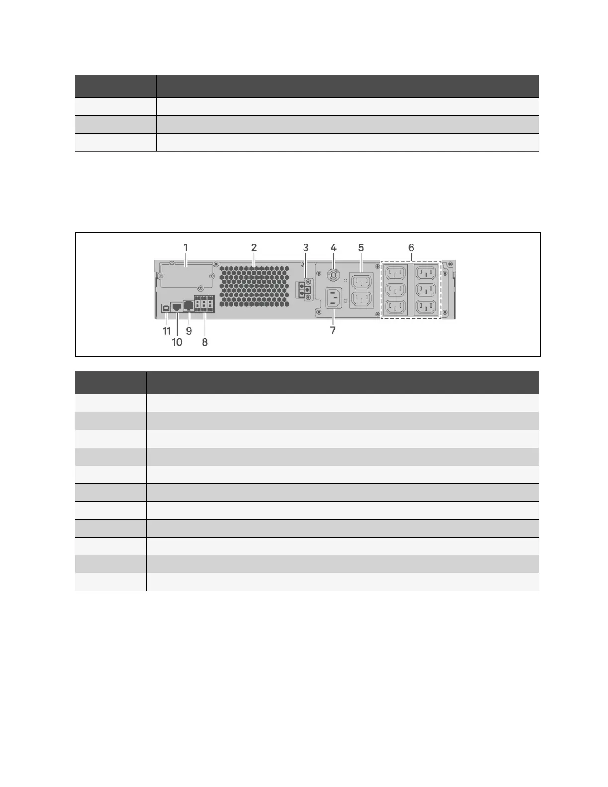
The following figures detail the rear panel features for each Vertiv™ Liebert® GXT5 model.
Figure 2.2 GXT5-750/1000IRT2UXL (XLE) Rear Panel
Item Description
1 Vertiv™ Liebert® IntelliSlot™ port
2 Ventilation hole
3 External battery Cabinets (EBC) connector
4 Input circuit breaker reset button, 10 A
5 Non-programmable C13 output receptacles
6 Programmable C13 output receptacles
7 C14 input-power plug and cable
8 Terminal-block communication connectors
9 RS-232 port - RJ-45/RJ-11 connection used for command line interface
10 RS-485 port - RJ-45 connection used for external temperature sensors
11 USB port
2 Product Description Proprietary and Confidential ©2024 Vertiv Group Corp. 5
Vertiv™ Liebert® GXT5 UPS Installer/User Guide