The USB port connects the UPS to a network server or other computer system. The USB port supports HID/CDC protocol.
The CDC protocol is reserved for service software. To use the HID protocol for monitoring, download Power Assist from
www.Vertiv.com/PowerAssist.
3.7.5 Connecting CLI Communication Cables
The UPS supports the Vertiv command line interface for operation with Vertiv ACS and other third party monitoring protocols.
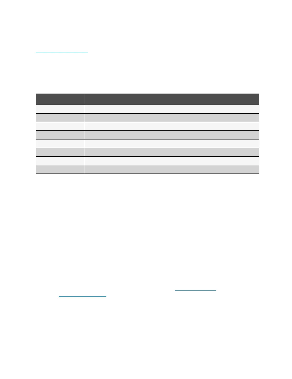
The RJ-45 port (labeled RS-232) is used for CLI connection. See the appropriate figure for your model in Rear Panels on
page5, for the location of the port. The pin-out, described in below table is consistent with the ACS pin-out.
Item Description
1 NC
2 NC
3 TXD (out)
4 GND
5 NC
6 RXD (in)
7 NC
8 NC
3.8 Installing a Parallel System
10 kVA, 16 kVA, and 20 kVA models may be configured in a parallel system. The UPS parallel system provides support to the
following options:
• 3 active systems
• 2 active systems
• 2 active systems plus 1 redundant system
• 1 active system plus 1 redundant system
All electrical requirements, including external distribution panel and branch circuit breaker, apply to each UPS in a parallel
system, which are then connected in ring configuration for redundancy and additional reliability. System load information can
be accessed via any controller/display in the system.
The following are requirements for the parallel connected system:
• Each UPS must have the same capacity and must be connected to the same mains/utility source.
• If a residual current detector (RCD) is required, if must be correctly set and installed before the same neutral line
input terminal. See safety and regulatory information, available at https://www.vertiv.com
ComplianceRegulatoryInfo.
• The output of each ups must be connected to the same output bus.
• The parameter configuration for each UPS must be identical.
46 Proprietary and Confidential ©2024 Vertiv Group Corp. 3 Installation
Vertiv™ Liebert® GXT5 UPS Installer/User Guide